Modeling of simultaneous switching noise in high speed systems

Modeling of Simultaneous Switching Noise in High
Speed Systems
Sungjun Chun,Student Member,IEEE,Madhavan Swaminathan,Senior Member,IEEE, Larry D.Smith,Member,IEEE,Jegannathan Srinivasan,Zhang Jin,Student Member,IEEE,and
Mahadevan K.Iyer,Member,IEEE
Abstract—Simultaneous switching noise(SSN)has become a major bottleneck in high speed digital design.For future systems, modeling SSN can be complex due to the thousands of intercon-nects that need to be analyzed.This is because a system level mod-eling approach is necessary that combines the chip,package and board level interactions.This paper presents an efficient method to model the SSN for high speed systems by developing circuit models for the planes and interconnections that can be combined using superposition theory.This approximation is valid at frequencies where skin effect is dominant.Simulation results are compared with the measurements on a test vehicle,verifying the validity of the method.In addition a system has been simulated to compute SSN,showing the application of this method for complex systems. Index Terms—Plane bounce,plane modeling,power distribution system,resonator model,return current,simultaneous switching noise.
I.I NTRODUCTION
C URRENT complementary metal oxide semiconductor
(CMOS)microprocessors and application-specific inte-grated circuits(ASICs)have hundreds of inputs/outputs(IOs) switching within one cycle time.When the noise produced by all the simultaneous switching circuits approaches the noise tolerance of a static CMOS circuit,the integrity of the output signal is degraded[1].Therefore proper prediction of the level of SSN in a packaged electronics system has become one of the most important issues in high frequency digital design.As electronic packaging has progressed from traditional lead frame packages to packages that have power and ground planes,the SSN problem has shifted from a lead frame inductance problem to a power plane inductance problem.In addition,the planes behave as cavity resonators at high frequencies which require the inclusion of both capacitance and resistance[2],[3].As inductances become smaller for future packaging technologies, it is our belief that the power plane contribution to SSN will dominate as compared to all inductive effects.Thus computing the response of planes in the presence of interconnects repre-sents the core of the SSN modeling problem,for future systems. All high frequency packages contain planes,which are used to supply power to the chips.A plane-pair,which consists of two
Manuscript received March29,2000;revised February26,2001.
S.Chun,M.Swaminathan,and J.Srinivasan are with the School of Elec-trical and Computer Engineering,Georgia Institute of Technology,Atlanta,GA 30332-0250USA.
L.D.Smith is with the Sun Microsystems,Palo Alto,CA94303USA.
Z.Jin and M.K.Iyer are with the Advanced Packaging Development Support Department,Institute of Microelectronics,Singapore117685.
Publisher Item Identifier S1521-3323(01)04073-4.planes(say Vdd and Gnd)separated by an insulator,behaves as a cavity resonator at high frequencies.When circuits such as output drivers switch,they deposit a time varying charge on the Vdd and Gnd planes which result in a displacement current source in the cavity.This current source excites radial electromagnetic waves inthe cavitythatreflectfromthe edgesofthe planes,causingmul-tipleresonancesinthecavity.Dependingontheimpedanceprofile of the cavity,which can contain multiple resonances,the planes can bounce causing voltage fluctuations on the power supply rails of the chip.This effect has been described in[3]where circuits in a microprocessor core switch simultaneously.This paper de-scribes a method for modeling the simultaneous switching noise for output drivers driving transmission lines in a multilayered package or board containing planes.
In[4],the SSN in the package has been modeled by extracting an effective inductance
L
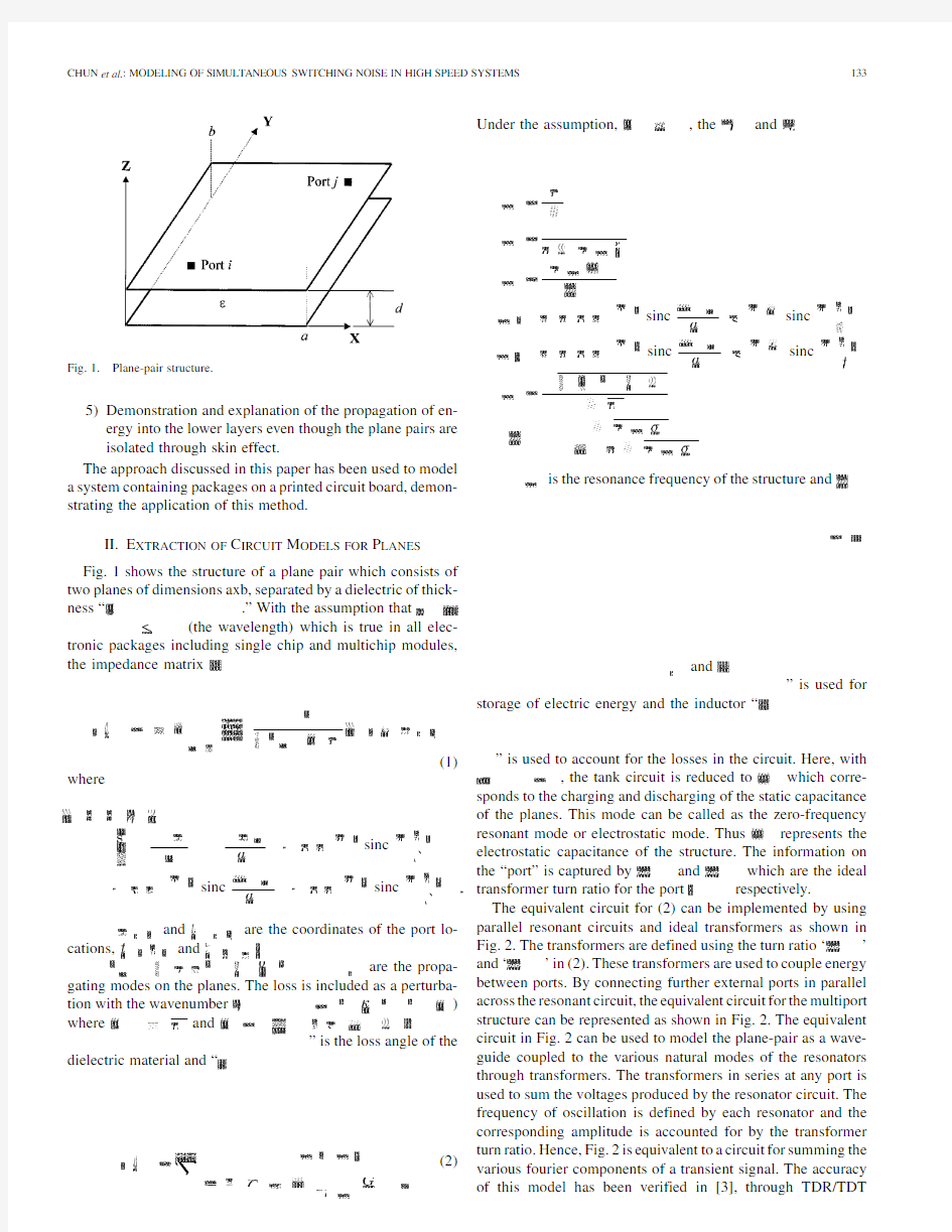
Fig.1.
Plane-pair structure.
5)Demonstration and explanation of the propagation of en-ergy into the lower layers even though the plane pairs are isolated through skin effect.
The approach discussed in this paper has been used to model a system containing packages on a printed circuit board,demon-strating the application of this method.
II.E XTRACTION OF C IRCUIT M ODELS FOR P LANES Fig.1shows the structure of a plane pair which consists of two planes of dimensions axb,separated by a dielectric of thick-ness
“
.”With the assumption
that (the wavelength)which is true in all elec-tronic packages including single chip and multichip modules,the impedance
matrix
(1)
where
sinc
sinc
sinc
and are the coordinates of the port lo-
cations,
and
are the propa-gating modes on the planes.The loss is included as a perturba-tion with the
wavenumber
)
where
and ”is the loss angle of the
dielectric material and
“
(2)
Under the
assumption,,
the
and
sinc
sinc
sinc
sinc
is the resonance frequency of the structure
and
and
”is used for
storage of electric energy and the inductor
“
”is used to account for the losses in the circuit.Here,
with
,the tank circuit is reduced
to which corre-sponds to the charging and discharging of the static capacitance
of the planes.This mode can be called as the zero-frequency
resonant mode or electrostatic mode.
Thus
represents the electrostatic capacitance of the structure.The information on
the “port”is captured
by
and which are the ideal transformer turn ratio for the port
respectively.The equivalent circuit for (2)can be implemented by using parallel resonant circuits and ideal transformers as shown in
Fig.2.The transformers are defined using the turn ratio
‘
’and
‘
’in (2).These transformers are used to couple energy between ports.By connecting further external ports in parallel across the resonant circuit,the equivalent circuit for the multiport structure can be represented as shown in Fig.2.The equivalent circuit in Fig.2can be used to model the plane-pair as a wave-guide coupled to the various natural modes of the resonators through transformers.The transformers in series at any port is used to sum the voltages produced by the resonator circuit.The frequency of oscillation is defined by each resonator and the corresponding amplitude is accounted for by the transformer turn ratio.Hence,Fig.2is equivalent to a circuit for summing the various fourier components of a transient signal.The accuracy of this model has been verified in [3],through TDR/TDT
Fig.2.Equivalent circuit for a plane-pair.
measurements.In addition,methods have been described in [3]to construct compact model representation of the planes.
The primary difference between the circuit described in [3]and Fig.2is the inclusion of the static mode using transformers
with turn
ratios
and m at 1GHz.As has been
discussed in [8],[9],the waves that propagate between planes induce current densities on the planes that decay exponentially as they penetrate through the conductor.If the plane thickness
‘
,
where 12ns.
Using 0.35/which corresponds to the 3dB frequency,the corresponding skin depth is
12.237
m,
which
is
,the skin effect approximation is valid.Based on this approximation,the plane layers and interconnection layers can be decoupled and stacked using superposition.In high speed systems with very fast rise times,the skin effect approximation will be increasingly valid for thick conductors.
It is important to understand the flow of charge at a port where a via makes contact to a plane.For a good conductor,the electric field across the two surfaces of the conductor has to be zero.This is equivalent to having an instantaneous flow of charge through the plane cross-section where a via makes contact to the plane surface.Hence,based on this assumption,for the plane structure in Fig.4(a),an equivalent circuit as shown in Fig.4(b)can be constructed where a short-circuit has been used to connect the two plane surfaces at any port.In Fig.4(b),the inductance of the via has been ignored,which can be included if necessary.This model can be readily extended to many layers.
In [3],(1)was used to compute the response of a multilayered plane structure under the assumption that skin effect was domi-nant.The results were correlated with the coupled transmission line model (CTL)described in [10].In this paper,since (1)has been linearized to (2)for constructing an equivalent circuit,the circuit model in Fig.4(b)has been compared with [10]to verify accuracy.
Thetest structureconsists of 3planeswith dimensions
of4in
2.5,and the separation between the local ground
plane and the global ground plane is 200mils with a relative di-electric
constant
1
in,5
in,
(a)
(b)
Fig.4.(a)Multilayered plane structure.(b)Equivalent circuit.
plane.Ports3and4are located at1in,
5in,
(a)
(b)
Fig.7.(a)Comparison of S13between result from Fig.6(solid line)and result from measurement (*).(b)Comparison of S14between result from Fig.6(solid line)and result from measurement (*).
This can be generated using a 2-D-solver and from the physical layout of the package or board.
V .T EST V EHICLE
A test vehicle was designed and measured to verify the va-lidity of the modeling method.Fig.9shows the test vehicle consisting of planes,transmission lines and nonlinear drivers.It is a seven-layered board with interconnects consisting of four
very wide microstrip transmission lines with
Z0
.They are about 20in (50cm)long and driven by a Texas Instruments ABT244buffer driver.The power and ground planes are 0.3in (7.6mm)wide and similar in length
to
(a)
(b)
Fig.8.(a)Microstrip configuration.(b)Unsymmetric stripline
configuration.
Fig.9.Test vehicle for SSN measurement.
the transmission lines.The stackup of the test vehicle in-cludes 4power planes and three signal layers in the order:sig1/Vdd1/Gnd1/sig2/sig3/Vdd2/Gnd2.The separation is 4
mils of FR4material between all copper layers except sig2 and sig3where the separation is24mils.Four silicon drivers are located on the left side of the test vehicle in a20pin DIP package.They were powered from Vdd1and Gnd1planes, using vias.Two sets of50
Fig.12.Measurement results:with termination.
driver and into the Gnd1plane,causing a deposition of posi-tive charge.On the Vdd1plane,the current leaves the vicinity of the driver as return current,leaving behind negative charge, as shown in Fig.11(b).This causes the accumulation of charges with opposite polarities on the planes in the vicinity of the driver. Since the charges vary with time,they are equivalent to a dis-placement current source,as shown in Fig.11(b).The current source excites a radial wave between the planes that bounces off the edges of the planes,causing the planes to bounce.
B.Test Case2
Consider the test case when the microstrip transmission lines are terminated with two43ohm resistors connected to both Vdd and Gnd planes on the right side of the test vehicle.This results in a different waveform,as shown in Fig.12.The maximum noise now occurs during the low to high transition instead of the high to low transition.This is due to the initial conditions on the transmission lines.Consider the initial condition when the driver is in the low state.Through the
43
microstrip transmission line.The pull-down device in the driver conducts the current to the local ground where it is returned back to the right side of the test vehicle through the Gnd1plane,as shown in Fig.13(a).The Vdd1-Gnd1planes are charged with the ground current.With these initial conditions,the driver makes a low to high tran-sition.When the pull-down device in the driver becomes high impedance,the initial current loop is opened.The current con-tinues to leave the ground node of the driver,leaving negative charge.Simultaneously the pull-up device connects the Vdd1 plane to the transmission line,causing the deposition of posi-tive charge on the Vdd1plane near the Vdd node of the driver as shown in Fig.13(b).The accumulation of charges near the driver acts like a displacement current source,exciting a distur-bance between the Vdd1-Gnd1plane,which causes the
planes
(a)
(b)
Fig.13.(a)Initial condition prior to low-to-high transition:with termination.
(b)Low-to-high transition:with termination.
to bounce.It is important to note that the direction of the cur-rent source is opposite to Test case1.This explains the opposite noise pattern for the two test cases.For the
22
Fig.14.Circuit model for the test vehicle.
has a plane beneath it and semi-infinite space above.Hence,the microstrip line can be represented as two transmission lines in parallel.The microstrip-plane combination can be modeled as a
transmission line with Z0and time delay
[ns]where
”is the length of the microstrip line in meters.This transmis-
sion line is referenced to the plane as decribed in Fig.8(a).The
microstrip-semi infinite space can be modeled to mimic a mi-
crostrip line with the plane at infinity,resulting in a transmission
line with large value(
1for air and“
0).InFig.14,
the input impedance looking into the parallel combination of the
two transmission lines is still Z0,which is the impedance
seen by the driver during switching.Similarly,the transmission
line beneath the bottom ground plane has been used to mimic the
semi-infinite space below the test vehicle.The circuit model in
Fig.14has been simulated in Spice by attaching nonlinear drivers
and compared to measured results in the next section.
IX.C ORRELATION WITH M EASUREMENT
The equivalent circuit for the test vehicle is shown in Fig.14,
where the number of modes used for the planes was
Gnd planes on the right side of the test vehicle with43
(a)
(b)
Fig.17.(a)Waveforms at the far end of striplines(strip1-strip4):no termination.(b)Waveforms at the far end of striplines(strip5-strip8):no termination.
to the time of flight required for the wave to propagate on the stripline to reach the far end of Strip1.An interesting phenom-enon can be observed in Strip4in Fig.17(a),where the near end is connected to Gnd2plane.Since Strip4carries the signal of the Gnd2plane with respect to Gnd1plane at the far end of the board,the result represents the amount of noise coupled to a quiet stripline that is referenced to a noisy power plane.In a sim-ilar manner,the noise coupled to a quiet stripline(Strip6)that propagates the Gnd1plane signal referenced to a noisy power plane(Vdd2plane)is shown in Fig.17(b).
X.S YSTEM L EVEL S IMULATION FOR SSN
In the previous sections,a method was presented for cap-turing the plane bounce on a test board.It consists of
sepa-Fig.18.Packaged system.
rate models for the planes and interconnections which are then combined to account for the return currents.In this section,the method has been extended for modeling a system containing packages on a printed circuit board.
The system is shown in Fig.18.The package consists of two planes(Vdd and Gnd)which
measures with a di-electric thickness of4mils.The insulator used was ceramic with a dielectric constant of nine.The PCB consists of two planes (Vdd and Gnd)with
size and a dielectric thickness of4mils.The insulator used was FR4with a dielectric constant of four.The PCB contains69decoupling capacitors which were distributed over the board at arbitrary locations near the pack-ages.Nine commercially available decoupling capacitors were used on the PCB.The capacitors were represented as a series RLC circuit where“R”and“L”are the series equivalent resis-tance and inductance of the capacitor,respectively.The PCB was powered using a1.5V supply at the upper left corner,as shown in Fig.18.
The two chips were connected using6transmission lines as shown in Fig.18.These transmission lines were connected to 22active drivers with rise time of100ps,which were switched simultaneously.Three transmission lines were referenced to the Vdd plane and the remaining three were referenced to the Gnd plane,both on the package and PCB.Chip C4s with inductance of0.05nH were used to connect the chip to the package.Simi-larly,solder balls with inductance of0.25nH were used to con-nect the package to the PCB.The planes in the package and PCB were connected together using solder balls with inductance of 0.25nH.A total of16C4s and16solder balls were used for the transmission lines for the driver and receiver chips and36 solder balls were used to connect between the package and PCB planes.
A total of nine modes were used to model the package planes while25modes were used for modeling PC
B planes.Fig.19 shows the noise measured on the power supply planes.Fig.19(a) is the noise measured on the package planes in the vicinity of the driver.The noise measured on the package planes in the vicinity of the receiver is shown in Fig.19(b).Both figures show a dis-tinct resonance in the waveforms due to the planes bouncing in the system.In addition,the noise on the receiver side is caused
(a)
(b)
Fig.19.(a)Power supply voltage fluctuation near drivers.(b)Power supply voltage fluctuation near receivers.
by the propagation of the electromagnetic wave through the PCB and package.
XI.C ONCLUSIONS
This paper describes an efficient method to model the SSN in multilayered packages and boards.The circuit models are first derived for the multiport power/ground planes.These models are then modified for the multilayered structure.Transmission lines were incorporated into the models based on superposi-tion theory.A test vehicle was designed and measured to ob-tain the plane-to-plane noise waveforms.The modeling method was correlated with measurements,showing the validity of the method.The simulation of the quiet embedded stripline trans-mission lines showed the amount of noise coupled to a quiet stripline that is referenced to a noisy power plane.It was demon-strated that using the method discussed in this paper,a system can be modeled to simulate plane bounce and its effect on driver and receiver switching.
R EFERENCES
[1]R.R.Tummala,E.J.Rymaszewski,and A.G.Klopfenstein,Microelec-
tronics Packaging Handbook.New York:Chapman&Hall,1997,pt.
I,pp.235–237.
[2]L.Smith,“Simultaneous switch noise and power plane bounce for
CMOS technology,”in Proc.IEEE8th Topical Meeting Elect.Perform.
Electron.Packag.,San Diego,CA,Oct.1999,pp.163–166.
[3]N.Na,J.Choi,S.Chun,M.Swaminathan,and J.Srinivasan,“Modeling
and transient simulation of planes in electronic packages,”IEEE Trans.
Comp.,Packag.,Manufact.Technol.B,vol.23,pp.340–352,Aug.2000.
[4]R.Senthinathan,A.C.Cangellaris,and J.L.Prince,“Reference plane
parasitics modeling and their contribution to the power and ground path ‘effective’inductance as seen by the output drivers,”IEEE Trans.Mi-crowave Theory Tech.,vol.42,pp.1765–1773,Sept.1994.
[5]W.Becker,B.McCredie,G.Wilkins,and A.Iqbal,“Power distribution
modeling of high performance first level computer packages,”in Proc.
IEEE2nd Topical Meeting Elect.Perform.Electron.Packag.,Oct.1993, pp.202–205.
[6]J.P.Libous and D.P.O’Connor,“Measurements,modeling,and simula-
tion of flip-chip CMOS ASIC simultaneous switching noise on a multi-layer ceramic BGA,”IEEE https://www.sodocs.net/doc/074844327.html,p.,Packag.,Manufact.Technol.
B,vol.20,pp.266–271,Aug.1997.
[7]T.Okoshi,Planar Circuits for Microwaves and Lightwaves.New
York:Springer-Verlag,1985,pp.10–42.
[8]J.Choi and M.Swaminathan,“Computation of the frequency response
of multiple planes in gigahertz packages and boards,”in Proc.IEEE8th Topical Meeting Elect.Perform.Electron.Packag.,San Diego,CA,Oct.
1999,pp.157–160.
[9]J.Mao,J.Srinivasan,J.Choi,N.Do,and M.Swaminathan,“Compu-
tation and effect of field penetration through planes in multilayered package power distribution networks for giga-processors,”in Proc.
IEEE9th Topical Meeting Elect.Perform.Electron.Packag.,Scottsdale, AZ,Oct.2000,pp.43–46.
[10]H.H.Wu,J.W.Meyer,K.Lee,and A.Barber,“Accurate power supply
and ground plane pair models,”IEEE Trans.Adv.Packag.,vol.22,pp.
259–266,Aug.1999.
[11]H.Johnson and M.Graham,High-Speed Digital Design.Englewood
Cliffs,NJ:Prentice Hall,pp.
189–191.
Sungjun Chun(S’00)received the B.S.degree
in electrical engineering from Chosun University,
Korea,in1997,the M.S.degree in electrical and
computer engineering from the Georgia Institute
of Technology(Georgia Tech),Atlanta,in2000,
where he is currently pursuing the Ph.D.degree in
electrical and computer engineering.
Since1998,he has been with the Packaging Re-
search Center,Georgia Tech,as a Graduate Research
Assistant.In1999,he worked at the Institute of Mi-
croelectronics,Singapore,as a summer intern.His research interest is in the area of the modeling and reduction of simultaneous switching noise in power distribution networks.
Madhavan Swaminathan(SM’99)received the M.S.E.E.and Ph.D.degrees in electrical engineering from Syracuse University,Syracuse,NY,in1989and 1991,respectively.
He is currently an Associate Professor in the School of Electrical and Com-puter Engineering,Georgia Institute of Technology(Georgia Tech),Atlanta.He is the Research Director at the Packaging Research Center,Georgia Tech.Before joining Georgia Tech,he was with the Advanced Technology Division,Pack-aging Laboratory,IBM,East Fishkill,NY,where he was involved with the de-sign,analysis,measurement,and characterization of packages for high perfor-
142IEEE TRANSACTIONS ON ADV ANCED PACKAGING,VOL.24,NO.2,MAY2001 mance systems.He has over100publications in refereed journals and confer-
ences,eight issued patents and two patents pending.He is the co-founder of
the IMAPS Next Generation IC and Package Design Workshop.He also serves
on the Technical Program Committees of EPEP,Signal Propagation on Inter-
connects Workshop,Solid State Devices and Materials Conference,and Inter-
pack.His research interests are in electromagnetic modeling,circuit modeling,
characterization and testing of high frequency digital and mixed signal ICs and
packages.
Dr.Swaminathan was co-author of the Best Student Paper Award at ECTC’96
and EPEP’00.He has been a Guest Editor for the IEEE T RANSACTIONS ON
A DV ANCED P ACKAGING and the IEEE T RANSACTIONS ON M ICROWA VE T HEORY
AND T ECHNIQUES.He served as the Co-Chair for the1998and1999IEEE Top-
ical Meeting on Electrical Performance of Electronic Packaging(EPEP),served
as the Technical and General Chair for the IMAPS Next Generation IC and
Package Design Workshop,serves as the Chair of TC-12,the Technical Com-
mittee on electrical design,modeling and simulation within the IEEE CPMT
Society,and is the Co-Chair for the2001IEEE Future Directions in IC and
Package Design Workshop.He is the co-founder of the IEEE Future Directions
in IC and Package Design Workshop.
Larry D.Smith(M’75)received the B.S.E.E.degree from the Rose Hulman
Institute of Technology,Terre Haute,IN,in1975and the M.S.degree in material
science from the University of Vermont,Burlington,in1983.
After joining IBM in1978,he worked in the areas of reliability,characteri-
zation,failure analysis,power supply and analog circuit design,packaging and
signal integrity.He has continued his efforts in signal integrity at Sun Microsys-
tems,Palo Alto,CA,since1996.His current area of concentration is design of
power distribution systems and reduction of simultaneous switch
noise.
Jegannathan Srinivasan was born in India on
June16,1958.He received the B.Tech.degree in
electrical engineering,the M.S.degree in Signal
processing techniques for range determination
in acoustical imaging,and the Ph.D.degree in
FFT-based algorithm on scattering and inverse
scattering from circular cylindrical shells,all from
the India Institute of Technology(IIT),Madras,in
1980,1986,and1991,respectively.
From1980to1983,he was a Research and
Development Engineer at Jaisun and Hutchison Private,Ltd.He was a Senior Project officer at IIT,Madras,from1991to1992. He joined the faculty of electrical engineering,University of Malaya,Kuala Lumpur,Malaysia,where he served from1992to1996.Subsequently he has held visiting scientific positions at the National Technical University of Athens, Athens,Greece;Department of Information Technology(INTEC),University of Ghent,Ghent,Belgium and the Packaging Research Center(PRC),Georgia Tech,Atlanta.His research interests include numerical solution of EM field problems,packaging,microwave engineering,inverse scattering problems, acoustical imaging,antennas,and digital image
processing.
Zhang Jin(S’98)received the B.Sc.degree in
microwave engineering from the University of Elec-
tronic Science and Technology of China,Chengdu,
in1994,the M.Eng.degree in electrical engineering
from the National University of Singapore in
2000,and is currently pursuing the Ph.D.degree
in electrical engineering at North Carolina State
University,Raleigh.
From July1994to November1997,she worked
as a Research Engineer in the Chengdu Institute of
Technology.Her research interests include the mod-eling,measurement,and design of high speed and performance packages and system,and microwave and millimeter-wave circuits
design.
Mahadevan K.Iyer(M’95)received the B.S.degree
in electronics engineering and physics and the M.S.
degree in microelectronics,both from the Indian
Institute of Technology,Madras,and the Ph.D.
degree in electronic packaging and interconnection
technologies for gigabit logic multichip modules
from Loughborough University of Technology,
Loughborough,U.K.
His16years of industrial experience covers device
and package characterization,EM modeling and RF
measurements,and multichip package development. He has more than25publications in refereed conferences and journals.He has been with the Institute of Microelectronics(IME),Singapore,since1996and is currently the R&D Manager of Advanced Packaging Development Department. Dr.Iyer received the Commonwealth Fellowship(UK)and John Guest Philips Merit Award(UK)for pursuing research in high frequency interconnection tech-nologies.He is a member of IMAPS and is currently serving as the President of IMAPS Singapore.
船舶原理
1.什么是船舶的浮性? 船舶在各种装载情况下具有漂浮在水面上保持平衡位置的能力 2.什么是静水力曲线?其使用条件是什么?包括哪些曲线?怎样用静水力曲线查某一吃水时的排水量和浮心位置? 船舶设计单位或船厂将这些参数预先计算出并按一定比例关系绘制在同一张图中;漂心坐标曲线、排水体积曲线;当已知船舶正浮或可视为正浮状态下的吃水时,便可在静水力曲线图中查得该吃水下的船舶的排水量、漂心坐标及浮心坐标等 3.什么是漂心?有何作用?平行沉浮的条件是什么? 船舶水线面积的几何中心称为漂心;根据漂心的位置,可以计算船舶在小角度纵倾时的首尾吃水;船舶在原水线面漂心的铅垂线上少量装卸重量时,船舶会平行沉浮;(1)必须为少量装卸重物(2)装卸重物p的重心必须位于原水线面漂心的铅垂线上 4.什么是TPC?其使用条件如何?有何用途? 每厘米吃水吨数是指船在任意吃水时,船舶水线面平行下沉或上浮1cm时所引起的排水量变化的吨数;已知船舶在吃水d时的tpc数值,便可迅速地求出装卸少量重物p之后的平均吃水变化量,或根据吃水的改变量求船舶装卸重物的重量 5.什么是船舶的稳性? 船舶在使其倾斜的外力消除后能自行回到原来平衡位置的性能。 6.船舶的稳性分几类? 横稳性、纵稳性、初稳性、大倾角稳性、静稳性、动稳性、完整稳性、破损稳性 7.船舶的平衡状态有哪几种?船舶处于稳定平衡状态、随遇平衡状态、不稳定平衡状态的条件是什么? 稳定平衡、不稳定平衡、随遇平衡 当外界干扰消失后,船舶能够自行恢复到初始平衡位置,该初始平衡状态称为稳定平衡当外界干扰消失后,船舶没有自行恢复到初始平衡位置的能力,该初始平衡状态称为不稳定平衡 当外界干扰消失后,船舶依然保持在当前倾斜状态,该初始平衡状态称为随遇平衡8.什么是初稳性?其稳心特点是什么?浮心运动轨迹如何? 指船舶倾斜角度较小时的稳性;稳心原点不动;浮心是以稳心为圆心,以稳心半径为半径做圆弧运动 9.什么是稳心半径?与吃水关系如何? 船舶在小角度倾斜过程中,倾斜前、后的浮力作用线的交点,与倾斜前的浮心位置的线段长,称为横稳性半径!随吃水的增加而逐渐减少 10.什么是初稳性高度GM?有何意义?影响GM的因素有哪些?从出发港到目的港整个航行过程中有多少个GM? 重心至稳心间的距离;吃水和重心高度;许多个 11.什么是大倾角稳性?其稳心有何特点? 船舶作倾角为10°-15以上倾斜或大于甲板边缘入水角时点的稳性 12.什么是静稳性曲线?有哪些特征参数? 描述复原力臂随横倾角变化的曲线称为静稳性曲线;初稳性高度、甲板浸水角、最大静复原力臂或力矩、静稳性曲线下的面积、稳性消失角 13.什么是动稳性、静稳性? 船舶在外力矩突然作用下的稳性。船舶在外力矩逐渐作用下的稳性。 14.什么是自由液面?其对稳性有何影响?减小其影响采取的措施有哪些? 可自由流动的液面称为自由液面;使初稳性高度减少;()减小液舱宽度(2)液舱应
现代教育技术读书笔记
《现代教育技术6-8章读书笔记》 第六章网络型课件的制作 网络的定义:网络是由节点和连线构成,表示诸多对象及其相互联系。 网络在中国的发展 第一阶段1987-1993年,研究试验阶段 第二阶段1994-1996,起步阶段 第三阶段1997年至今,是Internet在我国发展最为快速的阶段。 网络传播 网络传播有三个基本的特点:全球性、交互性、超文本链接方式。 定义:以全球海量信息为背景、以海量参与者为对象,参与者同时又是信息接受与发布者并随时可以对信息做出反馈,它的文本形成与阅读是在各种文本之间随意链接、并以文化程度不同而形成各种意义的超文本中完成的。 课件 课件是用于学校课堂计算机辅助教学的软件和电教教材。 课件包括:向学习者提示的各种教学信息。 用于对学习过程进行诊断、评价、处方和学习引导的各种信息和信息处理。 为了提高学习积极性,制造学习动机,用于强化学习刺激的学习评价信息。 用于更新学习数据、实现学习过程控制的教学策略和学习过程的控制方法。 课件的特点:整体性、固定性、封闭性、特定性。 网络课件的设计
(1)分析阶段 (2)总体设计 (3)网页编制与合成 (4)测试 (5)发布 (6)维护与更新 第七章信息技术与课程整合基本概念 信息技术教育应用发展概况 ①CAI(计算机辅助教学)阶段 ②CAL(计算机辅助学习)阶段 ③IITC(信息技术与课程整合)阶段 信息技术与学科课程的整合,就是通过将信息技术有效的融合于各学科的教学过程来营造一种新型教学环境,实现一种既能发挥教师主导作用,又能充分体现学生主体地位的意义,自主、探、究合作为特征的教与学方式,从而把学生的主动性积极性创造性较充分的发挥出来,是传统的以教师为中心的课堂教学结构,发生根本性变革,从而使学生的创新精神与实践能力的培养真正落到实处。 信息技术与课程整合的内涵包含三个基本属性:营造新型教学环境、实现新的教与学方式、变革传统教学结构。 美国教育技术CEO论坛提出了进行有效整合的步骤方法如下: ①确定教育目标,并将数字化内容与该目标联系起来。 ②确定课程整合应当达到的、可以被测量与评价的结果和标准 ③依据步骤1所确定的标准进行测量与评价,然后按评价结果对整合的方式做出相应的调
(完整版)现代教育技术重点考点整理
现代教育技术重点 第一章现代教育技术概论 第二节 1、教育技术:从广义上来说教育技术就是“教育中的技术”,是人类在教育活动中所采取的 一切技术手段和方法的总和。它分为有形的(物化形态)和无形的(智能形态) 两大类。单选或多选,小几率名词解释 2、美国教育传播与技术协会对教育技术的定义明确指出了教育技术的两个研究对象(学习 过程、学习资源)和五个研究领域(设计、开发、利用、管理和评价)妥妥的多选 (教育技术是对学习过程和学习资源进行设计、开发、利用、管理和评价的理论与实践3、教育技术的主要意义在于:利用系统科学对教育教学中存在的问题进行分析,提出解决 问题的策略和方法,进行实施并给予评价和修改,以实现教育教学的最优化,促进学习者的更好发展。 4、现代教育技术:是指以现代教育理论、学习理论为基础,以现代信息技术为主要技术手 段的教育技术。这里的现代信息技术主要是指计算机技术、多媒体技术、电子通讯技术、互联网技术、卫星广播电视技术、人工智能技术、虚拟现实仿真技术。妥妥多选 5、教育技术的发展历程(多选问几个阶段,单选问谁提出的,提了什么主张,重点) 视觉教育阶段(夸美纽斯和裴斯泰洛齐。倡导者强调的是利用视觉教材作为辅助,以使学习活动更为具体化,主张在学校课程中组合运用各种视觉教材, 将抽象的概念作具体化的呈现。) 视听教育阶段(戴尔提出以“经验之塔”为核心的“教学中的视听方法”。视听教学即为视觉材料、听觉材料或是其综合) 视听传播阶段 教育技术阶段(美国试听教育协会改名为教育传播和技术协会,简称AECT,1972年该协会将其实践和研究的领域正式名为教育技术,从此成为一门独 立的学科) 第三节 1、现代教育技术的意义多选 现代教育技术有效支撑教育改革 现代教育技术增强教学效果 现代教育技术促进教师专业发展 2、教育部于2004年12月(单选)正式颁布了《中小学教师教育技术能力标准(试行)》该 标准具体规定了相关人员的教育技术能力结构要求和达到各等级的培训所需的基本内容。下面是教学人员教育技术能力标准的体系结构与基本内容。 意识与态度 知识与技能 应用与创新 社会责任多选 第五节 一、学习理论(包含哪些理论) (一)行为主义学习理论(华生、巴甫洛夫、桑代克、斯金纳)选择题
船舶原理及结构课程教学大纲
文档来源为:从网络收集整理.word版本可编辑.欢迎下载支持. 《船舶原理与结构》课程教学大纲 一、课程基本信息 1、课程代码:NA325 2、课程名称(中/英文):船舶原理与结构/Principles of Naval Architecture and Structures 3、学时/学分:60/3.5 4、先修课程:《高等数学》《大学物理》《理论力学》 5、面向对象:轮机工程、交通运输工程 6、开课院(系)、教研室:船舶海洋与建筑工程学院船舶与海洋工程系 7、教材、教学参考书: 《船舶原理》,刘红编,上海交通大学出版社,2009.11。 《船舶原理》(上、下册),盛振邦、刘应中主编,上海交通大学出版社,2003、2004。 《船舶原理与结构》,陈雪深、裘泳铭、张永编,上海交通大学出版社,1990.6。 《船舶原理》,蒋维清等著,大连海事大学出版社,1998.8。 相关法规和船级社入级规范。 二、课程性质和任务 《船舶原理与结构》是轮机工程和交通运输工程专业的一门必修课。它的主要任务是通过讲课、作业和实验环节,使学生掌握船舶静力学、船舶阻力、船舶推进、船舶操纵性与耐波性和船体结构的基本概念、基本原理、基本计算方法,培养学生分析、解决问题的基本能力,为今后从事工程技术和航运管理工作,打下基础。 本课程各教学环节对人才培养目标的贡献见下表。
三、教学内容和基本要求 课程教学内容共54学时,对不同的教学内容,其要求如下。 1、船舶类型 了解民用船舶、军用舰船、高速舰船的种类、用途和特征。 2、船体几何要素 了解船舶外形和船体型线力的一般特征,掌握船体主尺度、尺度比和船型系数。 3、船舶浮性 掌握船舶的平衡条件、船舶浮态的概念;掌握船舶重量、重心位置、排水量和浮心位置的计算方法;掌握近似数值计算方法—梯形法和辛普森法。 2
心得体会现代教育技术考试培训学习笔记反思
现代教育技术考试培训学习笔记反思 现代教育技术考试培训学习笔记反思 忽如一夜春风来,千树万树梨花开 -- 现代教育应用技术培训学习心得体会 9月10日是我国第31个教师节,那天我有幸参加了县教育局组织的现代教育应用技术培训学习,在自己的节日对自己进行业务充电,让我感觉这个教师节过的充实、有意义。通过这次培训学习,我平时积累的关于一些电子白板的知识碎片得到了系统化升华,现将几点粗浅的体会,与同仁共勉: 电子白板是一种综合利用文字、图形、视频、声音等资源生动形象地展示教学内容的教学辅助工具,它在知识的抽象性和学生思维的形象性之间架起了一座桥梁,能让教师的教学游刃有余,让学生的学习兴趣盎然。 电子白板辅助教学最大的特点是有助于突出重点、分散难点。只要轻轻点击一下鼠标,它就可以创设丰富的活动情景,呈现出图文并茂、生动活泼的美景,这不仅为学生提供感知材料,而且可以在学习中的疑难之处,再现情境,把学生的兴趣激发出来。还能通过颜色、字体的变换,图像的闪烁,声音的变化,引起学生的有意注意,为学生的思考和探究做出提示。电子白板辅助教学的特点之二,能够将抽象的知识变成具体的东西表现出来。科学课上,没有实验条件的的情况下,一般都是老师凭空讲解,学生凭空想象来进行教与学,最好的时候也不过是有几张图片做参考。采用电子白板课件辅助教学,老师就可以在白板上模拟抽象
的东西,使教师讲课言之有物、具体实在,学生听课也不会云里雾里听不懂,课堂效果极佳。电子白板辅助教学的特点之三,能够提高学生的注意力,增强学生的理解力。语文课上,一些重点词句的理解都可以运用白板中的勾画、拖放、照相等功能,使学生的注意力迅速集中,在老师的讲解和学生的自读自悟中,学生的阅读理解力得到提高。电子白板辅助教学的特点之四,能够全面记录教学过程,便于学生复习和总结。电子白板教学,无论是老师的操作,还是学生答题的操作,都可以通过软件中的录播功能自动存储成视频文件,便于学生查找问题,进行总结和复习。 当今速度多变的时代,学生接触媒体比较多,接受知识的方法和学习方式也是多种多样的,这就要求我们教师一定要改变传统的教学方法与手段。电子白板是当前比较流行的教学辅助工具,作为教师我们要有一个正确的态度来对待,应该认真学习和应用,并且还要用好。我们的教学只有紧跟时代发展的潮流,与学生接受知识的方法紧密结合起来,才能立于不败之地。 (相衙镇中心小学王红燕)第二篇、中小学教师现代教育技术能力培 训心得体会现代教育技术考试培训学习笔记反思中小学教师现代教育技术能力培训心得体会这次参加了云南省中小学教师教育技术能力的培训,其中的课程:培训准备、编写教学设计方案、选择教学用的媒体、理解和熟悉信息化教学资源、信息化教学资源的收集与处理、信息化教学资源的集成与开发、形成完整的教学设计成果、教学设计的实施与评价反思、体验单元教学设计、培训的总结与提高。在现代教育理念与实
2020年研究生入学考试考纲
武汉理工大学交通学院2020年研究生入学考试大纲 2020年研究生入学考试考纲 《船舶流体力学》考试说明 一、考试目的 掌握船舶流体力学相关知识是研究船舶水动力学问题的基础。本门考试的目的是考察考生掌握船舶流体力学相关知识的水平,以保证被录取者掌握必要的基础知识,为从事相关领域的研究工作打下基础。 考试对象:2020年报考武汉理工大学交通学院船舶与海洋工程船舶性能方向学术型和专业型研究生的考生。 二、考试要点 (1)流体的基本性质和研究方法 连续介质概念;流体的基本属性;作用在流体上的力的特点和表述方法。 (2)流体静力学 作用在流体上的力;流体静压强及特性;压力体的概念,及静止流体对壁面作用力计算。 (3)流体运动学 研究流体运动的两种方法;流体流动的分类;流线、流管等基本概念。 (4)流体动力学 动量定理;伯努利方程及应用。 (5)船舶静力学 船型系数;浮性;稳性分类;移动物体和液舱内自由液面对船舶稳性的影响;初稳性高计算。 (6)船舶快速性 边界层概念;船舶阻力分类;尺度效应,及船模阻力换算为实船阻力;方尾和球鼻艏对阻力的影响;伴流和推力减额的概念;空泡现象对螺旋桨性能的影响;浅水对船舶性能的影响。 三、考试形式与试卷结构 1. 答卷方式:闭卷,笔试。 2. 答题时间:180分钟。 3. 试卷分数:总分为150分。 4. 题型:填空题(20×1分=20分);名词解释(10×3分=30分);简述题(4×10分=40分);计算题(4×15分=60分)。 四、参考书目 1. 熊鳌魁等编著,《流体力学》,科学出版社,2016。 2. 盛振邦、刘应中,《船舶原理》(上、下册)中的船舶静力学、船舶阻力、船舶推进部分,上海交通大学出版社,2003。 1
我对现代教育技术的认识
我对现代教育技术的认识 在信息技术飞速发展的今天,信息技术与课程整合的思想、理念和现代教育技术在教学应用中的重要意义不断的冲击着广大教育工作者。现代教育技术作为一种先进的教学手段和理念,以其先进独特的直观性、灵活性、实时性、立体化的优势,越来越受到广大教师和学生的青睐并对教育教学起到了积极的推动作用。现代教育技术已引起了教育领域的深刻变革,给教育观念、教学方法和教学组织形式等方面带来了深远的影响。深刻认识现代教育技术在教育教学中的重要地位及其相应的必要性和紧迫性,充分认识应用现代教育技术是现代科学技术和社会发展对教育的要求,是教育改革和发展的需要。因此,了解教育技术的发展历程,研究和掌握现代教育技术的基本理论与基本方法,洞察其发展趋势,才能跟上时代的发展步伐,以便在未来立于不败之地。 现代教育技术是运用现代教育理论和现代信息技术,通过对教与学过程和教与学资源的设计、开发、利用、评价和管理,以实现教学最优化的理论和实践,即是指应用于教育领域的现代科学技术。它包括教育、教学中应用的现代技术手段,即现代教育媒体;运用现代教育媒体进行教育、教学活动的方法,即传媒教学法;优化教育、教学过程的系统方法,即教学设计这三方面。现代教育技术在教学中的应用,主要体现为信息技术与课程的整合思想,是以实现信息技术与学科教学之间的“融合”,达到优化教育、教学过程的目的,它的本质是在先进的教育思想、教育理论的指导下,把以计算机及网络为核心的信息技术作为促进学生自主构建学习的认知工具、情感激励工具及丰富的教学环境的创设工具,并将这些工具全面地应用到各学科的教学过程中,使各种教学资源、各个教学要素和教学环节经过整理、组合,相互融合,从而达到培养学生创新精神与实践能力的目标。 现代教育技术的逐步普及与发展,为学科教学开拓了广阔的天地,在教学中有着积极的影响,具体表现如下:一、激发学生的学习兴趣,提高学生的课堂参与意识。“兴趣是最好的老师”,而形、色、声、像兼备的现代教学手段,常常如吸石般吸引着学生的注意力,这有利于启迪学生智慧,培养学生的学习积极性和主动性,真正成为学习的主体。二、扩充知识信息量,促进教学内容的快速更新。运用现代教育技术给学生的多重感官刺激和直观教学,加快了学生理解进程,相当于增强了学生的认知能力,从而缩短了学生对同样内容的接受时间,可以高效率、高质量地将大量信息传递给学生,特别是与计算机网络技术相融合,真正意义上实现了知识共享,最新知识的快速传播,有利于知识视野的拓宽。三、改变教育教学方法,有效提高教学效率。应用现代教育技术,能充分调动学生认识与实践的主观能动性,让学生真正成为学习的主人,教师不再是一个信息的主要提供者与学习的主导者,他将成为学生个别化学习探索活动的辅导者与支持者。现代教育技术手段用于教学就能解决传统教学方法中速度慢、范围窄的缺点,它具有速度快,知识信息量多而不乱、广而不泛的特点,能在有限的教学时限内最大限度的传授知识培养出基础厚,知识面宽的全方位人才。四、对教学资源的传播和再利用起到了积极作用。现代教育技术应用数字化教学材料,具有可以长久保存,可以通过网络技术或其它通讯手段广泛传播的特点,便于学生自学和教师交流。五、有力促进教学相长。现代媒体参与之后的课堂教学系统是“以学生为中心”的,教学信息的流向成为双向的,多维的,且学生的主体地位更为突出。由此,丰富多彩的教学环境,新颖活泼的教学方式很大程度地调动了学生学习的积极性,促进了学生和教师的交流。另外计算机网络与多媒体教学的结合,实现了学生与教师的立体三维互动,起到了教学相长的作用。 我国信息技术教育发展至今,虽然有长足的发展,但主要集中在城市和比较发达地区。特别是农村信息技术教育起步晚,发展缓慢,要达到普及和赶上发达国家的水平还有很大距离。现代教育技术的应用带来了教学效果和教学质量的提高,其中许多突出特点在实践中已显示了强大优势。但是任何事物的发展总是一个辨证的过程,在现代教育媒体开发与应用中
教学法学习笔记
教学法学习笔记 导论:从英语专业解读到师范课程学习 1了解我自己 2什么是大学?高等教育意味着什么? 3英语师范专业解读 4对2008级英语师范生的要求 专题壹: 英语教育专业素质能力及其发展 1 优秀或合格教师的标准维度有哪些? 2 英语教师成长与发展模式 3 英语教师成长和发展的类型目标:研究型教师 1)为什么要成为研究型教师 2)什么是“教学研究” 3)如何从事“教学研究” 专题贰 英语教师的角色定位: 从“普通教育”到“英语教学” (一)普通教育领域的教师角色论 1.什么是“角色”? 2、教师角色有何特点? 1)知识传播者、学习发动者、组织者和评定者 2)父母长者、朋友和管理员 3)榜样和模范公民 4)学生灵魂的塑造者 5)教育科学研究人员 (二)The role of the teacher in ELT 1)Harmer’s framework 2)New roles of teachers 3)Two aspects to the role of moral educator 4)邹为诚:教师必须摆脱过去的“教书匠”角色. 教师必须实现由“技术型”教师到“研究者型”教师的转变。 教师成为研究者(研究型外语教师) 教师必须发展课程开发能力, (教师作为课程开发者)应该成为课程开发的主体 教师的角色从传统的知识传递者转向学生学习促进者 教师的职能从传统的教书匠变为学习的引导者 教师自身必须是学习型的人(教师作为学习者) 作为学生学习的引导者 成为学生心理健康的维护者和学生的心理教育者 (教学)行动研究者 专题叁: 了解英语学习者 一教育心理学视野中的学习者:聚焦“青少年心理发展与教育”
《船舶原理与结构》课程教学提纲
《船舶原理与结构》课程教学大纲 一、课程基本信息 1、课程代码: 2、课程名称(中/英文):船舶原理与结构/Principles of Naval Architecture and Structures 3、学时/学分:60/3.5 4、先修课程:《高等数学》《大学物理》《理论力学》 5、面向对象:轮机工程、交通运输工程 6、开课院(系)、教研室:船舶海洋与建筑工程学院船舶与海洋工程系 7、教材、教学参考书: 《船舶原理》,刘红编,上海交通大学出版社,2009.11。 《船舶原理》(上、下册),盛振邦、刘应中主编,上海交通大学出版社,2003、2004。 《船舶原理与结构》,陈雪深、裘泳铭、张永编,上海交通大学出版社,1990.6。 《船舶原理》,蒋维清等著,大连海事大学出版社,1998.8。 相关法规和船级社入级规范。 二、课程性质和任务 《船舶原理与结构》是轮机工程和交通运输工程专业的一门必修课。它的主要任务是通过讲课、作业和实验环节,使学生掌握船舶静力学、船舶阻力、船舶推进、船舶操纵性与耐波性和船体结构的基本概念、基本原理、基本计算方法,培养学生分析、解决问题的基本能力,为今后从事工程技术和航运管理工作,打下基础。 本课程各教学环节对人才培养目标的贡献见下表。
三、教学内容和基本要求 课程教学内容共54学时,对不同的教学内容,其要求如下。 1、船舶类型 了解民用船舶、军用舰船、高速舰船的种类、用途和特征。 2、船体几何要素 了解船舶外形和船体型线力的一般特征,掌握船体主尺度、尺度比和船型系数。 3、船舶浮性 掌握船舶的平衡条件、船舶浮态的概念;掌握船舶重量、重心位置、排水量和浮心位置的计算方法;掌握近似数值计算方法—梯形法和辛普森法。
2019年上海交通大学船舶与海洋工程考研良心经验
2019年上海交通大学船舶与海洋工程考研良心经验 我本科是武汉理工大学的,学的也是船舶与海洋工程,成绩属于中等偏上吧,也拿过两次校三等奖学金,六级第二次才考过。 由于种种原因,我到了8月份才终于下定决心考交大船海并开始准备,只有4个多月,时间比较紧迫。但只要你下定决心,什么时候开始都不算晚,也不要因为复习得不好,开始的晚了就降低学校的要求,放弃了自己的名校梦。每个人情况不一样,自己好好做决定,即使暂时难以决定,也要早点开始复习。决定是在可以在学习过程中做的,学习计划也是可以根据自己的情况更改的。所以即使不知道考哪,每天学习多久,怎样安排学习计划,那也要先开始,这样你才能更清楚学习的难度和量。万事开头难,千万不要拖。由于准备的晚怕靠个人来不及,于是在朋友推荐下我报了新祥旭专业课的一对一,个人觉得一对一比班课好,新祥旭刚好之专门做一对一比较专业,所以果断选择了新祥旭,如果有同学需要可以加卫:chentaoge123 上交船海考研学硕和专硕的科目是一样的,英语一、数学一、政治、船舶与海洋工程专业基础(801)。英语主要是背单词和刷真题,我复习的时间不多,背单词太花时间,就慢慢放弃了,就只是刷真题,真题中出现的陌生单词,都抄到笔记本上背,作文要背一下,准备一下套路,最好自己准备。英语考时感觉着超级简单,但只考了65分,还是很郁闷的。数学是重中之重,我八月份开时复习,直接上手复习全书,我觉得没有必要看课本,毕竟太基础,而且和考研重点不一样,看了课本或许也觉得很难,但是和考研不沾边。计划的是两个月复习一遍,开始刷题,然后一边复习其他的,可是计划跟不上变化,数学基础稍差,复习的较慢,我又不想为了赶进度而应付,某些地方掌握多少自己心里有数,若是只掌握个大概,也不利于后面的学习。所以自打复习开始,我就没放下过数学,期间也听一些网课,高数听张宇、武忠祥的,线代肯定是李永乐,概率论听王式安,课可以听,但最主要还是自己做题,我只听了一些强化班,感觉自己复习不好的地方听了一下。我真题到了11月中旬才开始做,实在是太晚,我8月开始复习时网上就有人说真题刷两遍了,能不慌吗,但再慌也要淡定,不要因此为了赶进度而自欺欺人,做什么事外界的声音是一回事,自己的节奏要自己把握好,不然
心得体会 现代信息技术培训笔记
现代信息技术培训笔记 现代信息技术培训笔记 信息技术应用能力提升培训心得体会_培训心得体会 在这次培训当中,让我对教育现代化的发现有了新的认识,当今以计算机和网络技术为核心的现代技术正飞速的发展,改变我们的学习方式。信息的获取、分析、处理、应用的能力将作为现代人最基本的能力和素质的标志,同时对我们各方面的能力有了很大提高,特别是对信息技术的综合运用能力,现在已不只停留在课件的制作上。 一、理念上的更新 此次培训虽然是网上学习,但是培训都使我在观念上有一个更新。在平时我都停流在基本应用上,然而通过此培训,才真正的认识到自我在信息技术的运用上还有许多的不足,在今后的业务提升方面还有大量的知识要学习,只有这样随时为自我更新,补充新识,更新观念,从根本上提升专业素养。另外随着信息化快速发展,作为一名教师,必须具备良好的信息素养是终生学习、不断完善自身的需要。同样作为一名教师应具有现代化的教育思想、教学观念,掌握现代化的教学方法和教学手段,熟练运用信息工具(网络、电脑等)对信息资源进行有效的收集、加工、组织、运用;这些素质的养成就要求信息技术教师不断地学习,才能满足现代化教学的需要;信息素养成了终生学习的必备素质之一。 二、专业知识方面 通过聆听专家教授对“中小学教师信息技术能力标准解读”、“信息化
教学环境”专题与案例分析的学习,使我充认识到做为老师,首先要具备基本的信息素养,掌握信息操作的基本能力和获取信息的能力,除此之外还应具备信息收集处理以及表达的能力和综合运用能力。深刻的认识到教育信息的重要性,明白什么是教育信息化发的发展情况,真正理解了信息化教学环境在教育教学中的作用,掌握了几种常用的教学模式和软件的基本应用。通过聆听专家们对“资源检索与获取”、“多媒体素材的处理”、“办公软件综合应用”、多媒体课件设计与制作、微课设计与制作,等等的解析,才真正的意识到自己在专业知识方面太落后与不足。 三、细节上的渗透 本次培训中,专家教授们都注重细节上的教学渗透,他们通过专题讲与案例分析和演示操作的方式,不仅教给我们知识和技巧,更在无形中用自己的言行来引导大家,在一些细节的讲解上十分细致,恰当地渗透一些学科常识,使不同程度的老师都能得到提高,正真的学有所获。 通过这次培训我受益匪浅,这将在我今后的工作中有着非常重要的作用,我一定扎实工作,努力学习,把用所学到的教育技术知识更好地应用到现代化的教育教学中,做一名对学生负责,对学校负责,对社会负责的优秀教师。我会一如既往的学习各种关于信息技术的专业知识、持之以恒,不懈的努力优化自我的专业技能,更好的适应现代化社会的发展需求,培养新时代所需要的具有高信息技能的新兴人才。这将是我努力奋斗的目标!第二篇、现代教育技术笔记(完整版)
船舶原理整理资料,名词解释,简答题,武汉理工大学
第一章 船体形状 三个基准面(1)中线面(xoz 面)横剖线图(2)中站面(yoz 面)总剖线图(3) 基平面 (xoy 面)半宽水线图 型线图:用来描述(绘)船体外表面的几何形状。 船体主尺度 船长 L 、船宽(型宽)B 、吃水d 、吃水差t 、 t = dF – dA 、首吃水dF 、尾吃水dA 、平均吃水dM 、dM = (dF + dA )/ 2 } 、型深 D 、干舷 F 、(F = D – d ) 主尺度比 L / B 、B / d 、D / d 、B / D 、L / D 船体的三个主要剖面:设计水线面、中纵剖面、中横剖面 1.水线面系数Cw :船舶的水线面积Aw 与船长L,型宽B 的乘积之比。 2.中横剖面系数Cm :船舶的中横剖面积Am 与型宽B 、吃水d 二者的乘积之比值。 3.方型系数Cb :船舶的排水体积V,与船长L,型宽B 、吃水d 三者的乘积之比值。 4. 棱形系数(纵向)Cp :船舶排水体积V 与中横剖面积Am 、船长L 两者的乘积之比值。 5. 垂向棱形系数 Cvp :船舶排水体积V 与水线面积Aw 、吃水d 两者的乘积之比值。 船型系数的变化区域为:∈( 0 ,1 ] 第二章 船体计算的近似积分法 梯形法则约束条件(限制条件):(1) 等间距 辛氏一法则通项公式 约束条件(限制条件):(1)等间距 (2)等份数为偶数 (纵坐标数为奇数 )2m+1 辛氏二法则 约束条件(限制条件)(1)等间距 (2)等份数为3 3m+1 梯形法:(1)公式简明、直观、易记 ;(2)分割份数较少时和曲率变化较大时误差偏大。 辛氏法:(1)公式较复杂、计算过程多; (2)分割份数较少时和曲率变化较大时误差相对较小。 第三章 浮性 船舶(浮体)的漂浮状态:(1 )正浮(2)横倾(3)纵倾(4)纵横倾 排水量:指船舶在水中所排开的同体积水的重量。 平行沉浮条件:少量装卸货物P ≤ 10 ℅D 每厘米吃水吨数: TPC = 0.01×ρ×Aw {指使船舶吃水垂向(水平)改变1厘米应在船上施加的力(或重量) }{或指使船舶吃水垂向(水平)改变1厘米时,所引起的排水量的改变量 } (1)船型系数曲线 (2)浮性曲线 (3)稳性曲线 (4)邦金曲线 静水力曲线图:表示船舶正浮状态时的浮性要素、初稳性要素和船型系数等与吃水的关系曲线的总称,它是由船舶设计部门绘制,供驾驶员使用的一种重要的船舶资料。 第四章 稳性 稳性:是指船受外力作用离开平衡位置而倾斜,当外力消失后,船能回复到原平衡位置的能力。 稳心:船舶正浮时浮力作用线与微倾后浮力作用线的交点。 稳性的分类:(1)初稳性;(2)大倾角稳性;(3)横稳性;(4)纵稳性;(5)静稳性;(6)动稳性;(7)完整稳性;(8)非完整稳性(破舱稳性) 判断浮体的平衡状态:(1)根据倾斜力矩与稳性力矩的方向来判断;(2)根据重心与稳心的 相对位置来判断 浮态、稳性、初稳心高度、倾角 B L A C w w ?=d B A C m m ?=d V C ??=B L b L A V C m p ?=d A V C w vp ?=b b p vp m w C C C C C C ==, 002n n i i y y A l y =+??=-????∑[]012142...43n n l A y y y y y -=+++++[]0123213332...338n n n l A y y y y y y y --=++++++P D ?= P f P f x = x y = y = 0 ()P P d= cm TPC q ?= m g b g b g GM = z z = z BM z = z r z -+-+-
现代教育技术1
现代教育技术 1、信息技术的发展对高等教育的影响。 (一)教育信息化十年规划--总体目标 1、总体目标是“三基本两显著”,即:基本建成人人可享有优质教育资源的信息化学习环境,基本形成学习型社会的信息化支撑服务体系,基本实现所有地区和各级各类学校宽带网络的全面覆盖;教育管理信息化水平显著提高,信息技术与教育融合发展的水平显著提升。 2、教育信息化整体上接近国际先进水平,对教育改革和发展的支撑与引领作用充分显现。 (二)教育信息化十年规划—总体要求 1、教育信息化要为创新型人才培养提供基础支撑环境 ——利用信息技术手段,突破时空限制,推动教育体制、思想、观念、内容、方法、模式等方面的深刻变革,探索并推广以教材多媒体化、资源全球化、教学个性化、学习自主化、活动协作化、管理自动化、环境虚拟化为特征的新型信息化教育模式,实现信息技术与教学过程的有机整合,为素质教育、创新教育提供条件和基础支撑环境。 2、教育信息化要为推动科技进步、提高创新能力提供条件保障 ——加快科研环境的信息化建设,实现数据、资料、仪器设备等各种资源的整合共享和应用系统的互通操作,营造深层次共享的基础条件平台,提高师生和科研人员获取科技信息的速度和质量,提高网上科研协作水平,提高科研质量和水平,从而为自主创新能力的提高提供条件保障。 ——科研和学术交流的新工具,科技论文的写作面临变革,开放存取、出版模式变革。 (三)技术发展对教育的影响 1、教的工具逐渐改变(黑板,无尘,变白板。英国2007) 2、学的工具逐渐改变(课本,笔记本,电子pad。美国2010) 3、评的工具逐渐改变(纸笔,数码笔,学习过程,思维评估) 4、课的结构逐渐改变(知识传授在教室内,知识内化在教室外) 5、课的形态逐渐改变(45分,90分钟,讲,视频,5,10,20分钟)(四)大学要发挥人类文明的引领作用 1、大学作为文明社会中的重要组织机构,保持了较高的社会地位,而且经久不衰。大学不仅传承了知识文明,也曾经改变了它所处的时代。由于大学的荣誉地位和使命崇高,大学的任何重大变革都会引来保守势力的强烈反对。 2、MOOC的兴起,叩问传统大学:如果学生能用极低的费用在网上完
现代教育技术学笔记整理word文档良心出品
现代教育技术学笔记整 理 第一章:现代教育技术概述 1、信息时代教育的特点: 信息时代的教育 创新型、能力本位型; 凡是能提供学习环境、资源的地方; 辅助地位,知识的指导组织者 灵活便捷的个性 化教学, 混合教学 传统教育 知识型、学科本位型 以学校、教室为中心 主体地位,知识的传输者 整齐划一的班级授课教学, 说 ①教育目标: ②教学环境: ③教师地位: ④教学方式: 教性讲授 ⑤教学手段: 段 ⑥教学内容: ⑦教学资源: ⑧教学评价: ⑨教育制度: 2、 AECT 的定义: 概念:教育技术是为了 促进学习 (一个目标) ,对有关的 计、开发、运用、管理 和评价(五个领域)的 理论 与实践 启示: 1、理论与实践并重 2、 教育技术的核心方法是系统方法 3、与学习相关的过程是教育技术研究和实践的重要对象 4、学习资源是改善、优化学习过程的重要条件 3、 现代教育技术的定义: 现代教育技术是指在 现代教育理论 的指导下,充分而有效地 利用先进的技术与方法 ,通 过对教与学的过程和资源的创新性设计、开发、利用、管理和评价,来实现教与学优化的理 论与实践 。 “现代”的体现:★更多的注重、探讨与现代科技有关的课题; ★充分利用各种现代科技成果作为传 播教育信息的媒体 ★吸收科学的和现代的思维方法,使教育技术更科学化、系统化 4、 信息化教育定义: 信息化教育就是在现代教育思想和理论的指导下, 主要运用现代信息技术开发教育资源, 优化教育过程,以培养和提高学生信息素养为重要目标的一种新的教育方式。 信息素养 包括 信息意识 、 信息知识 、 信息能力 、 信息道德 等。 5、 现代教育技术: 20世纪 90 年代开始在我国使用; 研究对象是运用了先进技术的教学过程(如计算机、多媒体、网络、卫 星广播、虚拟 现实、人工智能等技术) 。 关注的主要是与先进技术相关的学习资源。 6、 视觉教育发展阶段( 20 世纪初至 20 世纪 30 年代) 最早使用视觉教育概念:美国 1906 年 《视觉教育》 1910 年,美国出版了第一本教学影片记录 7、 从视听教育到视听传播阶段( 20世纪 30年代至 20世纪 50年代) 1946 年,拉森制定研究生教学计划,首次开设视听教育课程,培养视听教育方面的的专 门人才。 利用现代多媒体技术开展教学 依靠粉笔, 黑板等传统教学手 根据教育需要,不断调整教学内容 以书本、电子课件、网络学习资源为主 多元化 评价方式 泛在学习、社会化学习、终身学习 1994” 很少改变 以书本为主 评价方式单一 学 校教学,仅针对在校学生 过程和资源 (两大对象)进行 设 两种性质)。
船舶原理题库
船舶原理试题库 第一部分船舶基础知识 (一)单项选择题 1.采用中机型船的是 A. 普通货船 C.集装箱船D.油船 2.油船设置纵向水密舱壁的目的是 A.提高纵向强度B.分隔舱室 C.提高局部强度 3. 油船结构中,应在 A.货油舱、机舱B.货油舱、炉舱 C. 货油舱、居住舱室 4.集装箱船的机舱一般设在 A. 中部B.中尾部C.尾部 5.需设置上下边舱的船是 B.客船C.油船D.液化气体船 6 B.杂货船C.散货船D.矿砂船 7 A. 散货船B.集装箱船C.液化气体船 8.在下列船舶中,哪一种船舶的货舱的双层底要求高度大 A.杂货船B.集装箱船C.客货船 9.矿砂船设置大容量压载边舱,其主要作用是 A.提高总纵强度B.提高局部强度 C.减轻摇摆程度 10 B.淡水舱C.深舱D.杂物舱 11.新型油船设置双层底的主要目的有 A.提高抗沉性B.提高强度 C.作压载舱用 12.抗沉性最差的船是 A.客船B.杂货船C散货船 13.横舱壁最少和纵舱壁最多的船分别是 B.矿砂船,集装箱船 C.油船,散货船D.客船,液化气体船 14.单甲板船有 A. 集装箱船,客货船,滚装船B.干散货船,油船,客货船 C.油船,普通货船,滚装船 15.根据《SOLASl974 A.20 B.15 D.10 16 A. 普通货船C.集装箱船D.散货船17.关于球鼻首作用的正确论述是 A. 增加船首强度
C.便于靠离码头D.建造方便 18.集装箱船通常用______表示其载重能力 A.总载重量B.满载排水量 C.总吨位 19. 油船的______ A. 杂物舱C.压载舱D.淡水舱 20 A. 集装箱船B,油船C滚装船 21.常用的两种集装箱型号和标准箱分别是 B.40ft集装箱、30ft集装箱 C.40ft集装箱、10ft集装箱 D.30ft集装箱、20ft集装箱 22.集装箱船设置双层船壳的主要原因是 A.提高抗沉性 C.作为压载舱 D. 作为货舱 23.结构简单,成本低,装卸轻杂货物作业效率高,调运过程中货物摇晃小的起货设备是 B.双联回转式 C.单个回转式D.双吊杆式 24. 具有操作与维修保养方便、劳动强度小、作业的准备和收尾工作少,并且可以遥控操 作的起货设备是 B.双联回转式 D.双吊杆式 25.加强船舶首尾端的结构,是为了提高船舶的 A.总纵强B.扭转强度 C.横向强度 26. 肋板属于 A. 纵向骨材 C.连接件D.A十B 27. 在船体结构的构件中,属于主要构件的是:Ⅰ.强横梁;Ⅱ.肋骨;Ⅲ.主肋板;Ⅳ. 甲板纵桁;Ⅴ.纵骨;Ⅵ.舷侧纵桁 A.Ⅰ,Ⅱ,Ⅲ,ⅣB.I,Ⅱ,Ⅲ,Ⅴ D.I,Ⅲ,Ⅳ, Ⅴ 28.船体受到最大总纵弯矩的部位是 A.主甲板B.船底板 D.离首或尾为1/4的船长处 29. ______则其扭转强度越差 A.船越长B.船越宽 C.船越大 30 A.便于检修机器B.增加燃料舱 D.B+C 31
考试大纲-重庆交通大学知识交流
硕士生入学复试考试《船舶原理与结构》 考试大纲 1考试性质 《船舶原理》和《船舶结构设计》均是船舶与海洋工程专业学生重要的专业基础课。它的评价标准是优秀本科毕业生能达到的水平,以保证被录取者具有较好的船舶原理和结构设计理论基础。 2考试形式与试卷结构 (1)答卷方式:闭卷,笔试 (2)答题时间:180分钟 (3)题型:计算题50%;简答题35%;名词解释15% (4)参考数目: 《船舶原理》,盛振邦、刘应中,上海交通大学出版社,2003 《船舶结构设计》,谢永和、吴剑国、李俊来,上海交通大学出版社,2011年 3考试要点 3.1 《船舶原理》 (1)浮性 浮性的一般概念;浮态种类;浮性曲线的计算与应用;邦戎曲线的计算与应用;储备浮力与载重线标志。 (2)船舶初稳性 稳性的一般概念与分类;初稳性公式的建立与应用;重物移动、
增减对稳性的影响;自由液面对稳性的影响;浮态及初稳性的计算;倾斜试验方法。 (3)船舶大倾角稳性 大倾角稳性、静稳性与动稳性的概念;静、动稳性曲线的计算及其特性;稳性的衡准;极限重心高度曲线;IMO建议的稳性衡准原则;提高稳性的措施。 (4)抗沉性 抗沉性的概念;安全限界线、渗透率、可浸长度、分舱因数的概念;可浸长度计算方法;船舶分舱制;提高抗沉性的方法。 (5)船舶阻力的基本概念与特点 船舶阻力的分类;阻力相似定律;阻力(摩擦阻力、粘压阻力、兴波阻力)产生的机理和特性。 (6)船舶阻力的确定方法 船模阻力试验方法;阻力换算方法;阻力近似计算的概念及方法;艾尔法、海军系数法等。 (7)船型对阻力的影响 船型变化及船型参数,主尺度及船型系数的影响,横剖面面积曲线形状的影响,满载水线形状的影响,首尾端形状的影响。 (8)浅水阻力特性 浅水对阻力影响的特点;浅窄航道对船舶阻力的影响。 (9)船舶推进器一般概念 推进器的种类、传送效率及推进效率;螺旋桨的几何特性。
现代教育技术读书笔记.
第三章信息化环境下的教学设计 信息化环境下的教学设计是运用系统方法,促进以学为中心的学习方式的转变,充分地、恰当地利用现代信息技术和信息资源,科学地安排教学过程的各个环节和要素,以实现教与学的最优化。信息化环境下的教学设计包括教学计划的设计、教学计划的执行、教学活动的评价与反馈。 教学设计的概念 什么是教学设计? 为了更清楚地理解这个概念,要先了解什么是教学和设计。美国的教育学家史密斯(P.LSmith 和拉根(T.J.Ragan 认为,教学就是信息的传递及促进学生达到预定、专门学习目标的活动。它是教育的一个分支,包含了学习、训练和讲授等活动。所谓设计,是指在进行某件事之前所做的有系统的计划过程或为了解决某个问题而实施的计划,它可以从精确性、细致性、系统性等方面去判断其效果的好坏。设计者必须以高度的精确和谨慎态度,具有系统计划一个方案的才能进行设计,否则,会导致时间的误用、资源的浪费甚至无效、沉闷和缺乏动机的学习。因此,设计应考虑许多可能影响实施计划或受计划实施所影响的因素。教学设计本是教学开发的重要组成部分,随着教学开发运动深人发展,推动了教学设计的研究,“自60年代以来,已逐渐发展成为教育技术领域的一门独立学科”。作为一门独立的学科概念本应有比较一致的认识,实则不然,从已经出版的教学设计著作和已发表的有关文章中,可以看出对其概念的界定,不论是内涵还是外延,都存在差别。归纳起来大致有如下一些说法:一是“计划”说。把教学设计界定义为是用系统的方法分析教学问题,研究解决问题途径。评价教学结果的计划过程或系统规划。这种论点的代表当推美国学者肯普,他给教学设计下的定义是:“教学设计是运用系统方法分析研究教学过程中相互联系的各部分的问题和需求”。在连续模式中确立解决它们的方法步骤,然后评价教学成果的系统计划过程。二是“方法”说。把教学设计看作是一种“研究教学系统、教学过程和制定教学计划的系统方法”。而这种方法与过去的教学计划不同,其区别就在于“现在说的教学设计有明确的教学目标,着眼于激发、促进辅助学生的学习,并以帮助每个学生的学习为目的。”三是“技术”说。鲍嵘在《教学设计理性及其限制》一文中认为,教学设计是一种“旨在促进教学活动程序化,精确化和合理
计算机辅助船舶制造(考试大纲)
课程名称:计算机辅助船舶制造课程代码:01234(理论) 第一部分课程性质与目标 一、课程性质与特点 《计算机辅助船体建造》是船舶与海洋工程专业的一门专业必修课程,通过本课程各章节不同教学环节的学习,帮助学生建立良好的空间概念,培养其逻辑推理和判断能力、抽象思维能力、综合分析问题和解决问题的能力,以及计算机工程应用能力。 我国社会主义现代化建设所需要的高质量专门人才服务的。 在传授知识的同时,要通过各个教学环节逐步培养学生具有抽象思维能力、逻辑推理能力、空间想象能力和自学能力,还要特别注意培养学生具有比较熟练的计算机运用能力和综合运用所学知识去分析和解决问题的能力。 二、课程目标与基本要求 通过本课程学习,使学生对船舶计算机集成制造系统有较全面的了解,掌握计算机辅助船体建造的数学模型建模的思路和方法,培养计算机的应用能力,为今后进行相关领域的研究和开发工作打下良好的基础。 本课程基本要求: 1.正确理解下列基本概念: 计算机辅助制造,计算机辅助船体建造,造船计算机集成制造系统,船体型线光顺性准则,船体型线的三向光顺。 2.正确理解下列基本方法和公式: 三次样条函数,三次参数样条,三次B样条,回弹法光顺船体型线,船体构件展开计算的数学基础,测地线法展开船体外板的数值表示,数控切割的数值计算,型材数控冷弯的数值计算。 3.运用基本概念和方法解决下列问题: 分段装配胎架的型值计算,分段重量重心及起吊参数计算。 三、与本专业其他课程的关系 本课程是船舶与海洋工程专业的一门专业课,该课程应在修完本专业的基础课和专业基础课后进行学习。 先修课程:船舶原理、船体强度与结构设计、船舶建造工艺学 第二部分考核内容与考核目标 第1章计算机辅助船体建造概论 一、学习目的与要求 本章概述计算机辅助船体建造的主要体系及技术发展。通过对本章的学习,掌握计算机辅助制造的基本概念,了解计算机辅助船体建造的特点、造船计算机集成制造系统的基本含义和主要造船集成系统及其发展概况。 二、考核知识点与考核目标 (一)计算机辅助制造的基本概念(重点)(P1~P5) 识记:计算机在工业生产中的应用,计算机在产品设计中的应用,计算机在企业管理中的应用,计算机应用一体化。 理解:CIM和CIMS概念,计算机辅助制造的概念和组成 (二)造船CAM技术的特点(重点)P6~P8 识记:船舶产品和船舶生产过程的特点,造船CAM技术的特点 理解:船舶产品和船舶生产过程的特点与造船CAM技术之间的联系 应用:造船CAM技术应用范围 (三)计算机集成船舶制造系统概述(次重点)(P8~P11)
相关文档
- 硕士生入学复试考试《船舶原理与结构》
- 船舶原理题库1
- 上海交通大学本科船海教材
- 江苏科技大学2017年《805船舶原理与结构》考研专业课真题试卷
- 2014年江苏科技大学船舶原理与结构考研真题考研试题硕士研究生入学考试试题
- 船舶原理第一、五~十章整理
- 2014年江苏科技大学考研试题 船舶原理与结构
- 上海交通大学本科船海教材
- 船舶原理(第九章 推力)
- 造船大意-第1~3章
- 船舶原理简答题
- sjtu船舶与海洋结构物设计制造专业研究生课程及参考书清单
- 船舶原理及结构课程教学大纲
- 船舶维修技术实用手册
- 船舶设计基础绪论和第一章讲解
- 哈尔滨工程大学-船舶设计原理考试复习答案最新最全
- 船舶设计原理(第3章)
- 船舶原理 下
- 船舶与海洋结构物设计制造方向
- 船舶原理与结构_习题之四(船舶操纵性)