建筑土木毕业设计中英文翻译5
一.英文原文
A NEW STAGGERED SHEAR WALL STRUCTURE FOR HIGH-RISE BUILDING
ABSTRACT
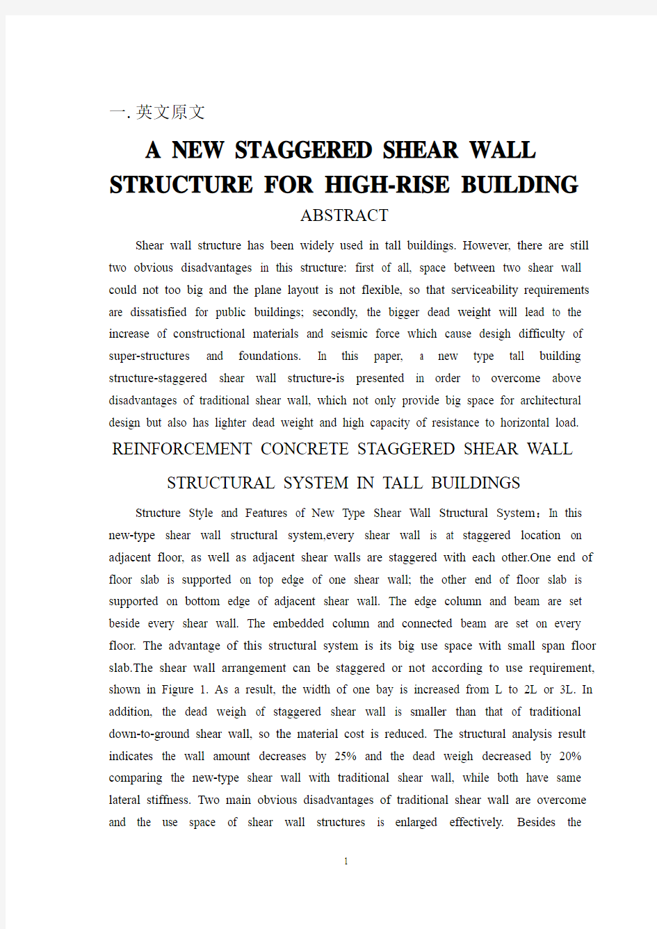
Shear wall structure has been widely used in tall buildings. However, there are still two obvious disadvantages in this structure: first of all, space between two shear wall could not too big and the plane layout is not flexible, so that serviceability requirements are dissatisfied for public buildings; secondly, the bigger dead weight will lead to the increase of constructional materials and seismic force which cause desigh difficulty of super-structures and foundations. In this paper, a new type tall building structure-staggered shear wall structure-is presented in order to overcome above disadvantages of traditional shear wall, which not only provide big space for architectural design but also has lighter dead weight and high capacity of resistance to horizontal load. REINFORCEMENT CONCRETE STAGGERED SHEAR WALL STRUCTURAL SYSTEM IN TALL BUILDINGS Structure Style and Features of New Type Shear Wall Structural System:In this new-type shear wall structural system,every shear wall is at staggered location on adjacent floor, as well as adjacent shear walls are staggered with each other.One end of floor slab is supported on top edge of one shear wall; the other end of floor slab is supported on bottom edge of adjacent shear wall. The edge column and beam are set beside every shear wall. The embedded column and connected beam are set on every floor. The advantage of this structural system is its big use space with small span floor slab.The shear wall arrangement can be staggered or not according to use requirement, shown in Figure 1. As a result, the width of one bay is increased from L to 2L or 3L. In addition, the dead weigh of staggered shear wall is smaller than that of traditional down-to-ground shear wall, so the material cost is reduced. The structural analysis result indicates the wall amount decreases by 25% and the dead weigh decreased by 20% comparing the new-type shear wall with traditional shear wall, while both have same lateral stiffness. Two main obvious disadvantages of traditional shear wall are overcome and the use space of shear wall structures is enlarged effectively. Besides the
architectural convenience, the staggered shear wall has other advantages. Although the stiffness of every shear wall is changed along vertical direction, the sum stiffness of whole structure is even along vertical direction when adjacent shear walls are set on staggered locations. The whole structural deformation is basically bending style. Form the analysis of reference,the staggered shear wall has stronger whole stiffness, less top-storey displacement(decreasing by about 58%),and less relative storey displacement comparing with traditional coupled shear wall.Under the same horizontal load, the staggered shear wall structure could effectively cut down the internal force of coupled beam and embedded column, at the same time the structural seismic performance is improved.
1 2
Working Mechanism of New Type Shear Wall Structure
Under the vertical load, this structure effect is the same as ordinary frame-shear wall structure, that is, the shear wall and column act together to resist the vertical load. Because the stiffness of every span shear wall is large and the deformation is small, the bending deformation and moment of columns are very small. Under lateral load, the structure deformation is uniform, thereby it can improve the whole stiffness effectively and the higher capability resisting lateral load is obtained.The main cause is the particular arrangement method of walls, which could be explained as follows: firstly, the lateral shearing force transfer mechanism is different from traditional shear wall. The lateral shearing force on top edge of shear wall is transferred to under layer floor slab though the bottom edge of wall, then to under storey adjacent shear wall through the under storey
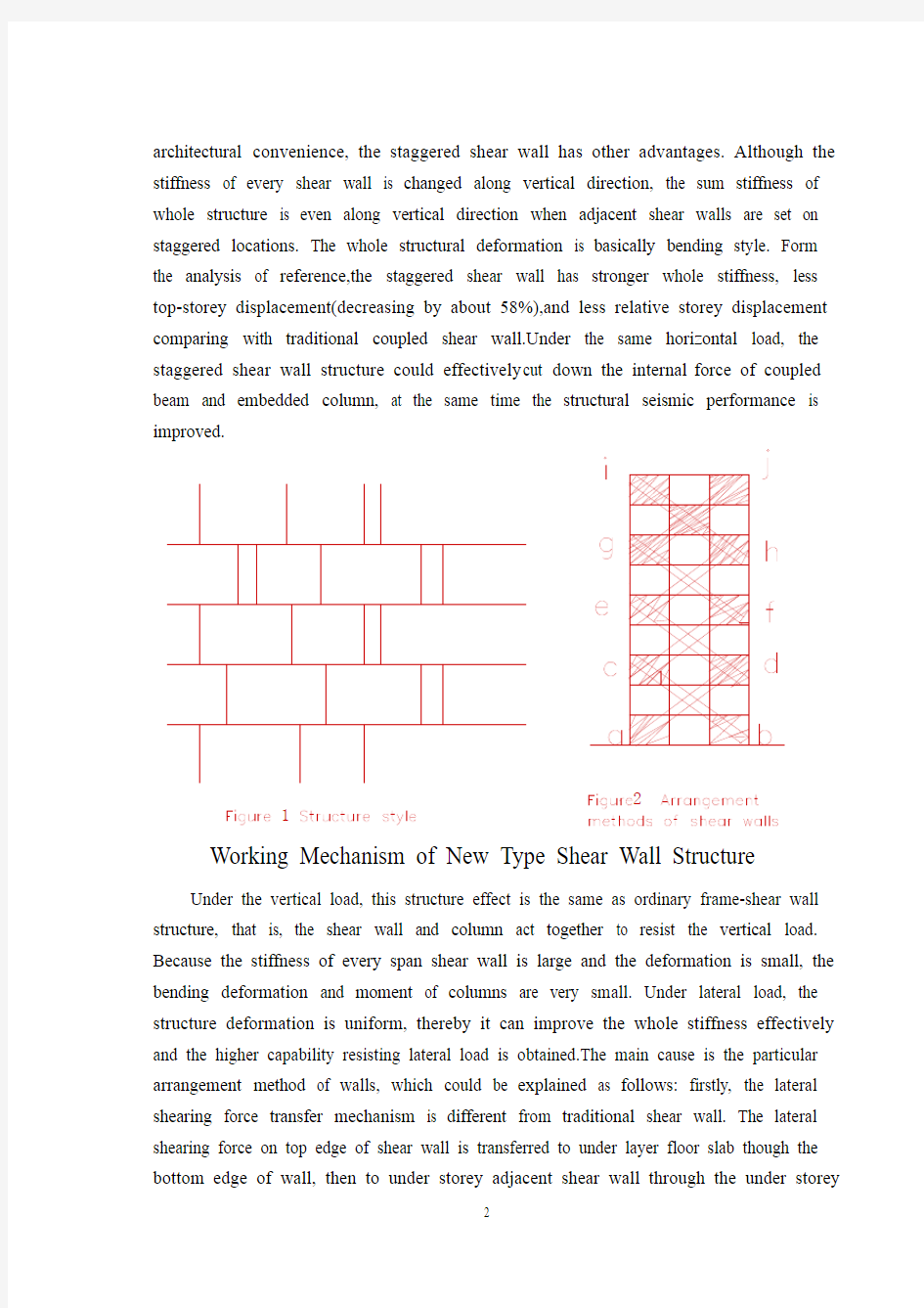
floor slab. At last, the lateral shearing force is transferred to ground floor shear wall and foundation.By this way,the lateral shearing force transfer mechanism is special, in which every floor slab transfer the lateral shearing force of itself floor and above floor.But in traditional shear wall directly. This structure makes the best use of the peculiarity that the slab stiffness is very strong to transfer and resist lateral shear. Although the shear walls are not up bottom in sequence, the slabs which has larger stiffness participate in the work transferring and resisting lateral shear force from the top to the down,from the floor middle part to edge, and from the edge to middle part in whole structure.It corresponds to a space integer structure with large lateral stiffness connected all shear walls by slabs, which have been cut in every story and span. It has been proved in author’s paper that the whole structure will occur integer-bending deformation under lateral force action,while every storey shear walls will occur integer bending without local bending. Secondly, in every piece of staggered shear wall (shown in Figure 2),the shear wall arrangement forms four large X diagonal brace along adcb,cfed, ehgf, gjih (dashed as shown in Figure 2).Because the shear walls forming X diagonal brace have large stiffness and strength, the X diagonal brace stiffness is strong. In addition, both the edge beams and columns around the boundary form bracing ‘frame”with large lateral stiffness. Hence, the structural integer stiffness is greatly improved.
Due to the above main reasons, this structure is considered to have particular advantages compared with traditional shear wall structure in improving structural lateral stiffness. It can provide larger using space, and reduce the material, earthquake action as well as dead weight.Also, it can provide larger lateral stiffness, which will benefit the structural lateral capability. In author’s paper and in this paper the example calculating results indicates that lateral stiffness of this structure are double of coupled shear wall structure ,and nearly equal to integer shear wall structure (light small than the latter).
Aseismic analysis and construction measures in a building
example
In order to study dynamic characteristics and aseismic performances in this structural system, the staggered shear wall will be used as all cross walls in the large bay shear wall structure without internal longitudinal walls.
Example. Thereis a nine-storey reinforcement concrete building, which is large bay shear wall struvture, shown in figure3. here,walls columns, beams, and slabs are all cast-in-situ. The thickness t=240mm is used for shear walls from 1 to 3 stories, while
thickness t=200mm is used for shear walls from 4 to 9 stories. Given the section of columns of width b=500mm and depth h=600mm . Given the section of beams of width b=300mm and depth h=700mm . The modulus of elasticity is assumed to be E=2.1*10E7
kN/2m and G=1.05*10E7 kN /2m . The external longitudinal walls are cast-in-situ wall frame, and the cross walls are staggered shear walls , showm in Figure 3 (a) (scheme I) ,intensity 8 zones near earthquake, 2type site ground 。The aseismic analysis is given by using the computer program FWD with wallboard element based on modal ayalysis response spectrum method 。 In order to compare ,the aseismic analysis of others are given at the same time , which are the cross walls used integer walls (scheme 2)and coupled walls (scheme3), shown in Figure 3 (a) and (b) ,respectively. The related results are listed in Table 1 and Table 2, where the seismic shear and displacement are all adopt from the SRSS result of formal three modal shapes.
3
Table1PeriodT(s) top-storey displancement △(cm) bottom seismic shearV(KN)
Wall layout
T1 T2 T3 △ V G V G α= Scheme Ⅰ
0.417 0.128 0.089 0.89 4088.3 56610 0.071 Scheme Ⅱ
0.376 0.110 0.057 0.78 6181.3 67500 0.092 Scheme Ⅲ 0.811 0.205 0.092
1.94 2519.9 60660 0.042
Table 2 Every-story displancement △(cm)
Number of stories SchemeⅠSchemeⅡSchemeⅢ
9 0.890 0.780 1.940
8 0.812 0.695 1.647
7 0.686 0.605 1.381
6 0.604 0.512 1.143
5 0.472 0.415 0.909
4 0.372 0.31
5 0.658
3 0.239 0.220 0.426
2 0.161 0.13
3 0.233
1 0.056 0.059 0.074
From the abve calculated results , it can be observed, firstly , that the building bay increased from 7.2m(scheme 2,3) to 7.2*2=14.4m (scheme 1 ) .Therefore, the useable floor area is increased greatly while dead weight is decreased 2093kN, and concrete of shear walls is saved (40% compared with scheme 2 or about 25% compared with scheme 3). Because the structural stiffness based on the arrangement method of shear walls is uniform, the whole lateral stiffness is increased a lot than that of schene 3 and close to scheme 2 , however, the seismic force is decreased greatly due to the decrease of dead weight ,which reduce the bottom shear coefficient a from 0.092 (scheme 2) to 0.071, thereby it can solve problems in traditional shear wall structures with light increase of the top-storey displancement ( scheme 1 only increases 0.11 cm than scheme 2 ), such as larger bottom shear seismic coefficient . Compared with coupled wall (scheme 3), this structure obviously advances lateral stiffness that the top-storey displancement ?=0.89cm is about 45% of the coupled wall ?=1.94cm .However, the concrete amount and dead weight reduce 25 % than that of coupled wall. This result shows that the new type struvture can adjust the structural stiffness and reduce eigher dead weight or seismic force when the solid shear wall with small opening, which has large stiffness , dead weight , seismic force , and material amount , is dissatisfied because the section of shear walls and height of coupied beams are limited in design .In this structure, the lateral shear force cannot be transferred to bottom directly but though slabs because the shear walls are cut in ecery storey. Due to the large shear force transferred to the bottom slabs ,
as a result , the slabs in first storey should be strengthened to ensure that the adequate strength and stiffness would be obtained to transfer the lateral shear force the structure need .
In general, the slabs are cast-in-situ. The concrete used for slabs normally should have grade strength of no less than C20 .The thickness of slabs should not less than 180mm , especially in bottom stories in which the distribution bars are two-way reinforcement ф8 @200. It is emphasized that the shear constructions should be strengthened at the joints-shear walls and slabs . In order to ensure shear strength between walls and slabs ,the wall bars should extend into the above and below spans for a distance according to related Code avout development length .Furthermore, the joint stresses of above and below shear walls are so complex that the shear failure or the lailure caused by the used except the embedded column and connected beam to ensure the joint strength and stiffness. At the above and below walls intersects the fillet measure must be used . Other aseismic constructional details should be carried out in accordance with the Code involved in shear wall structure.
Conclusions
From the above analysis and research, the following conclusions can be drawn : (1) Compare with traditional shear wall structures , the staggered shear wall structure has many advantages, such as providing bigger space and lateral stiffness ,reducing dead weight and seismic force , and saving constructional materials . therefore, this structural system has good economic benefits .
(2) the structural stiffness and deformation is uniform, thereby it can improve the whole stiffness effectively and enable it to appear wholly bending state, which are beneficial to increase the capacity of resistance to horizontal force and ductility.
(3) This structure can reduce the bottom shear seismic coefficient of shear wall structures, thereby it can solve many problems in ordinary shear wall structures , such as bigger space and lateral stiffness , and higher seismic force which will lead to bigger bottom shear seismic coefficient . It also can be a efficient method adjusting structural stiffness and dead weigh in design .
(4)This structure can be used in longitudinal wall of big-space shear wall structure without inner longitudinal wall, cross shear wall and longitudinal frame structure, and fishy bone big space shear wall structure , because it can provide bigger space and reduce superstructure dead weigh and seismic action without reducing stiffness, which benefit
resistance either ground floor frame-supported shear wall or whole structure.
(5) This structure can be used in non-seismic regions and has good effect because it can provide bigger lateral stiffness than ordinary shear wall structures, which have the same amount of shear walls. So it is beneficial to resist wind loads. Where specific aseismic design and construction measure are taken, it can be used in intensity 7 or 8 seismic zones.
(6) Alternate-floor shear wall structure has been used overseas in practical engineering and has good effect. However, it can only be used in the single-span structures. The staggered shear wall structure presented in this paper can be used in the multi-span structures, which has better behaviors of stiffness uniformity along the height and deformation than the former.
This new type structural system of tall buildings needs further research, especially need to be checked by model experiments and engineering practices.
新型高层建筑物结构交错排列剪力墙结构
引言
剪力墙结构在高层建筑用途广泛。然而,在这个结构中仍然有二个明显的缺点:首先,二个剪力墙之间的空间不可能太大,并且平面布局不灵活,因此不满足公共建筑的操作性能要求; 第二,更大的自重将导致建设材料和地震力的增大从而造成结构和基础设计困难。在本文,为了克服普通剪力墙的缺点介绍一个新型高层建筑结构交错排列的剪力墙结构,不仅为建筑设计提供大空间,而且对水平作用力的抵抗有更轻自重和抵抗力。
交错排列剪力墙结构系统在高层建筑中的具体优点新型剪力墙结构系统样式和特点:在这个新型剪力墙结构系统,每个剪力墙的交错排列地点设在毗邻地板上,并且毗邻剪力墙相互交错排列. 一剪力墙上缘支撑地面板的一个末端; 毗邻剪力墙下缘支撑地面板的另一个末端。在每个剪力墙旁边设置边柱和梁。在每个地面板上设置嵌入柱和连系梁。这个结构系统的好处是它的空间用途大和板的间距小。剪力墙可以交错排列或不符合使用要求,见图1。结果,间隔宽度从L被增加到2L或3L。. . 另外,交错排列的剪力墙自重小于普通剪力墙,因此减少物质费用。结构分析结果表明新型剪力墙与普通剪力墙相比,在两者有同样侧向刚度时,墙壁数减退25%和自重减少20%。不仅克服了普通剪力墙的二个主要明显的缺点,并且有效地扩大剪力墙结构用途空间。除了建筑便利以外,交错排列的剪力墙还有其他好处。虽然每个剪力墙的刚度变形沿垂直的方向,当毗邻剪力墙在交错排列地点受力时,整体结构的总刚度变形沿垂直的方向。整体结构变形基本上弯曲形式。以上分析表明,交错排列的剪力墙和普通剪力墙相比有更强的整体刚度、较少的上面层位移(减少大约58%)和较少的相对楼层位移。在同一水平力之下,交错排列剪力墙结构能有效地减少梁和柱的内力,并且在地震时提高结构的性能。
新型剪力墙结构工作方法
在垂直力作用下,这个结构作用和普通框架结构一样,剪力墙和柱一起抵抗垂直力。由于每个剪力墙的刚度大,并且变形小,柱的弯曲的变形和弯曲时间是非常小的。在侧向力作用下,结构变形是一致的,从而它可能有效地改进整体刚度,并且能更好的抵抗侧向力。主要原因是剪力墙的特殊布置方法,可以解释如下:首先,侧向剪切力传递方法是与传统剪力墙不同。侧向剪切力通过墙壁下缘从剪力墙上缘转移到下层楼板,然后通过下面楼板到下面楼层毗邻剪力墙。最后,侧向剪切力转移到基层剪力墙和基础。由此可知,侧向剪切力传递方法是特别的,每个
楼板通过楼板和上层楼板传递侧向剪切力。但在传统剪力墙结构中,每个楼板只传递自身的侧向剪力。横向剪切力通过剪力墙直接传递给基础。这个结构充分利用板的大刚度来传递并且抵抗横向剪力。虽然剪力墙底部排列不规则,但在整体结构中,楼板有更大的刚度,它传递和抵抗从上到下的侧向剪力,从地板中间渐近或从边缘到中间的侧向剪力。它相当于空间整体结构有了大侧向刚度,它通过楼板连接被楼层和跨度隔开的所有剪力墙。在作者的文章中证明了在侧向力作用下整体结构将发生整体弯曲变形,而每个楼层剪力墙将发生弯曲,不会发生局部弯曲。
图2 剪力墙的布置方法
图1 结构形式
第二,在交错排列的剪力墙每个部分(如图2所示),剪力墙沿对角线adcb,cfed,ehgf,gjih排列成四个X形(如图2所示)。由于形成X对角线,剪力墙有大刚度和强度,X对角线具有教大的刚度。另外,边柱和梁形成了具有教大侧向刚度的支撑--`框架”。因此,很大地增强结构整体刚度。由于上述主要原因,这个结构与普通剪力墙结构相比,在增强结构侧向刚度方面有特殊的意义。它可以扩大使用空间,并且减少材料,在地震作用时减轻自重。并且,它可能提供更大的侧向刚度,有益于增强结构侧向能力。在作者的想法和本文例子的计算的结果表明这个结构通过连接两个剪力墙产生的侧向刚度几乎和整体剪力墙结构相同(比后者轻)。
在大厦这个例子中的抗震分析和建筑措施
为了学习这个结构系统的力学性能和抗震能力,交错排列的剪力墙在结构不使用内纵墙的情况下将被用于大跨度结构的横墙。
例子。有一个九层的混凝土建筑,是跨度剪力墙结构,如上图3所示。这里,墙、柱、梁和楼板全部采用现浇。从1到3层使用厚度t=240mm的剪力墙,从4
到9层使用厚度t=200mm剪力墙。假如柱的宽度b=500mm,高度h=600mm。假如梁的宽度b=300mm,高度h=700mm。假设弹性模量E=2.110E7 kN/㎡和G=1.05×10E7 kN/㎡。如上图3 (a) 所示(方案Ⅰ),8度震区,2类地面附近,外纵墙被浇注框架中,并且横墙是交错排列的剪力墙。在分析反应光谱方法分析墙板元素的基础上,使用计算机程序FWD计算抗震的分析。为了比较,在上图3 (a)和(b)同时给出了其它的抗震的分析,分别显示横墙使用的整体墙(方案2)和联肢墙(方案3)。
相关结果在表1和表2中列出,地震作用力和位移全部从SRSS结果中采取。
图3 墙的布置
表一周期T(s),顶点位移△(cm),底部剪力V(KN)
墙的布置T1 T2 T3 △V G V
α=
G
方案Ⅰ0.417 0.128 0.089 0.89 4088.3 56610 0.071
方案Ⅱ0.376 0.110 0.057 0.78 6181.3 67500 0.092
方案Ⅲ0.811 0.205 0.092 1.94 2519.9 60660 0.042
表二各层位移
层号方案Ⅰ方案Ⅱ方案Ⅲ
9 0.890 0.780 1.940
8 0.812 0.695 1.647
7 0.686 0.605 1.381
6 0.604 0.512 1.143
5 0.472 0.415 0.909
4 0.372 0.31
5 0.658
3 0.239 0.220 0.426
2 0.161 0.13
3 0.233
1 0.056 0.059 0.074
由上面的结果可知,这个结构还得经受检验,首先,大厦跨度从7.2m (方案2,3)增加到7.2×2=14.4m (方案1)。在自重减少10890kN的同时增加房屋的使用面积,而且荷载减少了2093kN,并且保护了剪力墙的混凝土(40%和方案2比较或大约25%和方案3比较)。由于这样布置的剪力墙的结构刚度是一样的,和方案3和方案2相比整体侧向刚度增加很多,然而,自重的减少导致了地震力地减少,使底部剪力系数a从0.092 (计划2) 降低到0.071,因此它有可能解决普通剪力墙结构的顶点位移变化小的问题(计划1比计划2仅增加0.11 cm),例如更大的底部剪力系数。
和联肢墙相比(计划3),这个结构的上层侧向刚度位移明显增加了0.89cm,大约是联肢墙的45%( =1.94cm)。然而,混凝土用量和自重比连接墙减少了25%。这个结果表示,当坚固的剪力墙有小裂缝时,会具有大刚度、大自重和地震力,此新型结构可以调整结构刚度和减少自重或地震力,美中不足的是在设计时限制了部分剪力墙和梁。. 在这个结构中,因为剪力墙在每个楼层是间断的,所以侧向剪切应力是不可能直接地通过板传递到底部。由于有较大剪切力传递到底部板,因此,一层板应该具有更大的强度和刚度来传递剪切力.
一般来说,采用现浇板。板的混凝土强度不得低于比C20。板的厚度不应该少于180mm,特别是底层应铺设ф8 @200的双向钢筋。在剪力墙和板的连接处应加大强度。为了保证墙和板之间的抗剪强度,根据与计算长度有关的规范,斜杆应具有一定的锚固长度。而且,在剪力墙上下连接处应力十分复杂以至于剪力墙很容易出现斜裂缝从而造成剪切破坏。所以除了暗柱和连梁以外,在剪力墙的连接处应设置斜杆来保证连接处的强度和刚度。. 在墙上下相交处必须使用内圆角措施。其它抗震的措施的使用应与剪力墙结构的抗震规范相一致。
总述:
从上述分析和研究,得到以下结论:
1) 和传统剪力墙结构相比,交错排列剪力墙结构有许多好处,例如提供更大的空间和侧向刚度,减少自重和地震力和保护建筑材料。因此,这个结构系统有教好经济效益。
2) 结构刚度和变形是一致的,从而它可以有效地改进整体刚度,使结构出现完全弯曲状态,增加对水平作用的抵抗力和延展性。
3) 这个结构可以减少剪力墙结构的底部剪力系数,从而可以解决许多问题,例如大空间和侧向刚度以及可以增大底部剪力系数的地震力。在设计时是一个调整结构刚度的高效率的方法。
4) 在没有内纵墙、十字型剪力墙和纵向框架结构以及不牢固的大空间剪力墙结构时,这个结构可以用于大空间剪力墙结构的纵墙,因为它可以提供更大的空间和减少结构自重和地震力,无需减少刚度,有益于任何框架的剪力墙或整体结构。
5) 这个结构可以用于非地震地区并且有教大的作用,因为它在有相同数量剪力墙的情况下,和普通的剪力墙结构相比,可以提供更大的侧向刚度。这样,对抵抗风荷载有教大的作用。在采用抗震设计和建筑措施的情况下,可以用于7或8级震区
6) 交错剪力墙结构在外国工程中被应用并有很好的作用。但是,它只用于单间距结构。在本文提出了交错排列剪力墙结构可以用于多间距结构,和前者相比刚度能更好的沿垂直方向发生变形。
这个新型高层建筑结构系统需要进一步的研究,特别是需要由模型实验和工程学实践检查。
毕业设计外文翻译资料
外文出处: 《Exploiting Software How to Break Code》By Greg Hoglund, Gary McGraw Publisher : Addison Wesley Pub Date : February 17, 2004 ISBN : 0-201-78695-8 译文标题: JDBC接口技术 译文: JDBC是一种可用于执行SQL语句的JavaAPI(ApplicationProgrammingInterface应用程序设计接口)。它由一些Java语言编写的类和界面组成。JDBC为数据库应用开发人员、数据库前台工具开发人员提供了一种标准的应用程序设计接口,使开发人员可以用纯Java语言编写完整的数据库应用程序。 一、ODBC到JDBC的发展历程 说到JDBC,很容易让人联想到另一个十分熟悉的字眼“ODBC”。它们之间有没有联系呢?如果有,那么它们之间又是怎样的关系呢? ODBC是OpenDatabaseConnectivity的英文简写。它是一种用来在相关或不相关的数据库管理系统(DBMS)中存取数据的,用C语言实现的,标准应用程序数据接口。通过ODBCAPI,应用程序可以存取保存在多种不同数据库管理系统(DBMS)中的数据,而不论每个DBMS使用了何种数据存储格式和编程接口。 1.ODBC的结构模型 ODBC的结构包括四个主要部分:应用程序接口、驱动器管理器、数据库驱动器和数据源。应用程序接口:屏蔽不同的ODBC数据库驱动器之间函数调用的差别,为用户提供统一的SQL编程接口。 驱动器管理器:为应用程序装载数据库驱动器。 数据库驱动器:实现ODBC的函数调用,提供对特定数据源的SQL请求。如果需要,数据库驱动器将修改应用程序的请求,使得请求符合相关的DBMS所支持的文法。 数据源:由用户想要存取的数据以及与它相关的操作系统、DBMS和用于访问DBMS的网络平台组成。 虽然ODBC驱动器管理器的主要目的是加载数据库驱动器,以便ODBC函数调用,但是数据库驱动器本身也执行ODBC函数调用,并与数据库相互配合。因此当应用系统发出调用与数据源进行连接时,数据库驱动器能管理通信协议。当建立起与数据源的连接时,数据库驱动器便能处理应用系统向DBMS发出的请求,对分析或发自数据源的设计进行必要的翻译,并将结果返回给应用系统。 2.JDBC的诞生 自从Java语言于1995年5月正式公布以来,Java风靡全球。出现大量的用java语言编写的程序,其中也包括数据库应用程序。由于没有一个Java语言的API,编程人员不得不在Java程序中加入C语言的ODBC函数调用。这就使很多Java的优秀特性无法充分发挥,比如平台无关性、面向对象特性等。随着越来越多的编程人员对Java语言的日益喜爱,越来越多的公司在Java程序开发上投入的精力日益增加,对java语言接口的访问数据库的API 的要求越来越强烈。也由于ODBC的有其不足之处,比如它并不容易使用,没有面向对象的特性等等,SUN公司决定开发一Java语言为接口的数据库应用程序开发接口。在JDK1.x 版本中,JDBC只是一个可选部件,到了JDK1.1公布时,SQL类包(也就是JDBCAPI)
毕业设计外文翻译附原文
外文翻译 专业机械设计制造及其自动化学生姓名刘链柱 班级机制111 学号1110101102 指导教师葛友华
外文资料名称: Design and performance evaluation of vacuum cleaners using cyclone technology 外文资料出处:Korean J. Chem. Eng., 23(6), (用外文写) 925-930 (2006) 附件: 1.外文资料翻译译文 2.外文原文
应用旋风技术真空吸尘器的设计和性能介绍 吉尔泰金,洪城铱昌,宰瑾李, 刘链柱译 摘要:旋风型分离器技术用于真空吸尘器 - 轴向进流旋风和切向进气道流旋风有效地收集粉尘和降低压力降已被实验研究。优化设计等因素作为集尘效率,压降,并切成尺寸被粒度对应于分级收集的50%的效率进行了研究。颗粒切成大小降低入口面积,体直径,减小涡取景器直径的旋风。切向入口的双流量气旋具有良好的性能考虑的350毫米汞柱的低压降和为1.5μm的质量中位直径在1米3的流量的截止尺寸。一使用切向入口的双流量旋风吸尘器示出了势是一种有效的方法,用于收集在家庭中产生的粉尘。 摘要及关键词:吸尘器; 粉尘; 旋风分离器 引言 我们这个时代的很大一部分都花在了房子,工作场所,或其他建筑,因此,室内空间应该是既舒适情绪和卫生。但室内空气中含有超过室外空气因气密性的二次污染物,毒物,食品气味。这是通过使用产生在建筑中的新材料和设备。真空吸尘器为代表的家电去除有害物质从地板到地毯所用的商用真空吸尘器房子由纸过滤,预过滤器和排气过滤器通过洁净的空气排放到大气中。虽然真空吸尘器是方便在使用中,吸入压力下降说唱空转成比例地清洗的时间,以及纸过滤器也应定期更换,由于压力下降,气味和细菌通过纸过滤器内的残留粉尘。 图1示出了大气气溶胶的粒度分布通常是双峰形,在粗颗粒(>2.0微米)模式为主要的外部来源,如风吹尘,海盐喷雾,火山,从工厂直接排放和车辆废气排放,以及那些在细颗粒模式包括燃烧或光化学反应。表1显示模式,典型的大气航空的直径和质量浓度溶胶被许多研究者测量。精细模式在0.18?0.36 在5.7到25微米尺寸范围微米尺寸范围。质量浓度为2?205微克,可直接在大气气溶胶和 3.85至36.3μg/m3柴油气溶胶。
建筑类外文文献及中文翻译
forced concrete structure reinforced with an overviewRein Since the reform and opening up, with the national economy's rapid and sustained development of a reinforced concrete structure built, reinforced with the development of technology has been great. Therefore, to promote the use of advanced technology reinforced connecting to improve project quality and speed up the pace of construction, improve labor productivity, reduce costs, and is of great significance. Reinforced steel bars connecting technologies can be divided into two broad categories linking welding machinery and steel. There are six types of welding steel welding methods, and some apply to the prefabricated plant, and some apply to the construction site, some of both apply. There are three types of machinery commonly used reinforcement linking method primarily applicable to the construction site. Ways has its own characteristics and different application, and in the continuous development and improvement. In actual production, should be based on specific conditions of work, working environment and technical requirements, the choice of suitable methods to achieve the best overall efficiency. 1、steel mechanical link 1.1 radial squeeze link Will be a steel sleeve in two sets to the highly-reinforced Department with superhigh pressure hydraulic equipment (squeeze tongs) along steel sleeve radial squeeze steel casing, in squeezing out tongs squeeze pressure role of a steel sleeve plasticity deformation closely integrated with reinforced through reinforced steel sleeve and Wang Liang's Position will be two solid steel bars linked Characteristic: Connect intensity to be high, performance reliable, can bear high stress draw and pigeonhole the load and tired load repeatedly.
建筑学专业英语翻译
建筑学专业英语翻译 1.1 新建筑时代的文化融合 Since the 1990s, China has obviously speeded up its steps to open the architectural field to the outside world. That is fully testified by its extensive adoption of the competition mechanism,introducing intern ati onal bidd ing for some importa nt con structi ons. As a result, visi ons of domestic architects have been expanded, t heir mentality updated, and a number of prominent masterworks created.The successful biddi ng for quite a few major projects by foreig n architects marks the begi nning of Chin a's accession into the international community in the architectural sector. 自20 世纪90 年代开始,中国明显力口快了向世界开放建筑领域的步伐,此事通过中国广泛采纳竞争机制,为一些重要建筑引入国际招标可以得到充分证 实。由此,国建筑师的眼见得以被扩充,心态得到升华,大量的知名建筑被创造。大量的重要建筑项目被国外的建筑师成功中标,标志着在建筑面中国融入国际社会的开始。 Just like the country's accession into the World Trade Organization, which originally provoked controversies among some Chinese people who worried aboutabout the fate of the domestic enterprises, only a temporary sacrifice of domestic architectural sectors can create cha nces for theirfuture success in ever- in creas ing intern ati onal competiti ons. 正如中国加入世界贸易组织一样,一些中国人担心国企 业的命运,只是暂时牺牲国建筑行业,在不断增加的国际竞争中创造未来的成功几会。 We still remember the words sighed out by a participating Chinese group of architects after the first round of review of the desig ning biddi ng for the Nati onal Cen ter for the Perform ing Arts. "We admit our in feriority to foreign competitors," they said. 我们还记得一个参与表演艺术中心投标的中国团队的建筑师们在 第一轮审查之后的叹气。我们承认相比外国竞争对手我们的劣势,“他们说。
毕业设计英文翻译
使用高级分析法的钢框架创新设计 1.导言 在美国,钢结构设计方法包括允许应力设计法(ASD),塑性设计法(PD)和荷载阻力系数设计法(LRFD)。在允许应力设计中,应力计算基于一阶弹性分析,而几何非线性影响则隐含在细部设计方程中。在塑性设计中,结构分析中使用的是一阶塑性铰分析。塑性设计使整个结构体系的弹性力重新分配。尽管几何非线性和逐步高产效应并不在塑性设计之中,但它们近似细部设计方程。在荷载和阻力系数设计中,含放大系数的一阶弹性分析或单纯的二阶弹性分析被用于几何非线性分析,而梁柱的极限强度隐藏在互动设计方程。所有三个设计方法需要独立进行检查,包括系数K计算。在下面,对荷载抗力系数设计法的特点进行了简要介绍。 结构系统内的内力及稳定性和它的构件是相关的,但目前美国钢结构协会(AISC)的荷载抗力系数规范把这种分开来处理的。在目前的实际应用中,结构体系和它构件的相互影响反映在有效长度这一因素上。这一点在社会科学研究技术备忘录第五录摘录中有描述。 尽管结构最大内力和构件最大内力是相互依存的(但不一定共存),应当承认,严格考虑这种相互依存关系,很多结构是不实际的。与此同时,众所周知当遇到复杂框架设计中试图在柱设计时自动弥补整个结构的不稳定(例如通过调整柱的有效长度)是很困难的。因此,社会科学研究委员会建议在实际设计中,这两方面应单独考虑单独构件的稳定性和结构的基础及结构整体稳定性。图28.1就是这种方法的间接分析和设计方法。
在目前的美国钢结构协会荷载抗力系数规范中,分析结构体系的方法是一阶弹性分析或二阶弹性分析。在使用一阶弹性分析时,考虑到二阶效果,一阶力矩都是由B1,B2系数放大。在规范中,所有细部都是从结构体系中独立出来,他们通过细部内力曲线和规范给出的那些隐含二阶效应,非弹性,残余应力和挠度的相互作用设计的。理论解答和实验性数据的拟合曲线得到了柱曲线和梁曲线,同时Kanchanalai发现的所谓“精确”塑性区解决方案的拟合曲线确定了梁柱相互作用方程。 为了证明单个细部内力对整个结构体系的影响,使用了有效长度系数,如图28.2所示。有效长度方法为框架结构提供了一个良好的设计。然而,有效长度方法的
中英对照建筑学经典词汇
外立面:facade 跨度:Span 坡道:ramp 砍墙:Hom wall 墙面:Metope 铝合金:aluminium alloy 透明中空玻璃:transparent insulating glass 隔墙:partition 檩条;purlin 库板:panel, board 加气砼砌块: aerated concrete block 矿棉:mineral wool 水泥砂浆:cement mortar 抹灰/粉刷:plastering 轻钢龙骨:lightgage steel joist 石膏板:Plasterboard 托盘架: pallet rack 台阶坡道散水工程Steps ramp apron work 零星工程:Piecemetal works Drumming line 灌装站 Isotainer yard 标准槽灌堆场 Eurotint building 胶衣配色间 防火分区:fire compartment 石砌块墙体:masonry wall 内外:interior exterior 液压卸货平台:hydraulic dock leveler 地勘报告:geology survey 土层分布:soil layer distribution 预应力砼管桩:pre-stressed concrete tubular pile 岩土:geotechnical/rock soil 荷载:load 电缆桥架:Cable tray 沉降:sedimentation 密度:density 防爆荧光灯:anti-blast fluorescent lamp 插座:outlet 探测器:detector/sensor 配电盘,开关板; switch board 管架:pipe bridge 开工:commencement 开办费:Preliminary cost 维护:maintenance 建立:setup 主体:main body
土木工程毕业设计中英文翻译
附录:中英文翻译 英文部分: LOADS Loads that act on structures are usually classified as dead loads or live loads are fixed in location and constant in magnitude throughout the life of the the self-weight of a structure is the most important part of the structure and the unit weight of the density varies from about 90 to 120 pcf (14 to 19 KN/m)for lightweight concrete,and is about 145 pcf (23 KN/m)for normal calculating the dead load of structural concrete,usually a 5 pcf (1 KN/m)increment is included with the weight of the concrete to account for the presence of the reinforcement. Live loads are loads such as occupancy,snow,wind,or traffic loads,or seismic may be either fully or partially in place,or not present at may also change in location. Althought it is the responsibility of the engineer to calculate dead loads,live loads are usually specified by local,regional,or national codes and sources are the publications of the American National Standards Institute,the American Association of State Highway and Transportation Officials and,for wind loads,the recommendations of the ASCE Task Committee on Wind Forces. Specified live the loads usually include some allowance for overload,and may include measures such as posting of maximum loads will not be is oftern important to distinguish between the
建筑学专业英语翻译
Exhibition Hall Art Gallery In Bonn 波恩美术展览馆 这个建筑坐落在波恩市博物馆的旁边,非常地醒目,它是另一个建立在这个庞大正方形基础上的建筑,(它的)平行六面体的每条底边均长达95.7米,该建筑还有一个高11米的平台,可以栽种树木,有一个可供展览的花园以及恍如天堂般的曲径小道;上面还建有三个突出的焦点——3痤园锥体塔楼,屹立在开阔的风景线上,3面用于内部采光的天窗就是该建筑的标识了。 主通道位于东北方,通向与博物馆共享的公共区域,布满了像迷宫一样呈网状分布的小型植物。沿着弗里德里希·埃伯特大道,往东北方向或有些阻碍——11根柱子分列于两痤恢宏大厦之间,柱上点缀着一些纵向的充满韵律感的浮雕,象征并代表着十一个领域所取得的丰功伟绩。从这些柱子开始,地面上的一道时髦的白色线条引领着人们直达入口,一条又长又窄的阶梯将人们从这个区域引向最高的天台。 这个入口门厅是虚化处理的平行六面体结构,穿过它的就来到另一个外部天井,门厅的表面朝两个方向分别布满了光滑的波纹状和对角形斜纹。 这个正方形基础,已按9×9m的网形布局进行过调整,分为一个沿边的环状带和四个内部区域,即入口门厅,有观众席的讨论区,主馆和中央大厅。 外围的地带包括办公室,商店,会议室,图书馆,经典画廊。它露出了它自己在屋顶上覆盖了西南一半的天窗,(通过天窗)将自己从花园中分离出来。 展览的地方提供了一个独特的可供小型、中型、大型房间单独使用的同时,其或以不同方式合并的系统。 主馆是一个大的、呈长方形、两层高的空间,它被在两个侧面的天窗和对面角落里的锥形光明塔照亮。在中央大厅,有一个双跑的楼梯爬上墙壁、庭院和内部的双重空间。两者结合起来形成的中心广场的空间被上层的房间包围。在背叠式风格里,在这个楼层和双重空间里,可以找到对应的第二光塔的圆形大厅。第三个(光塔的圆形大厅)位于建筑的东北- 西南轴上,这个轴线包含了一个集合在门厅和礼堂之间的部分大厅、一个在东南外立面上的三层双跑楼梯的后门。
毕业设计外文翻译
毕业设计(论文) 外文翻译 题目西安市水源工程中的 水电站设计 专业水利水电工程 班级 学生 指导教师 2016年
研究钢弧形闸门的动态稳定性 牛志国 河海大学水利水电工程学院,中国南京,邮编210098 nzg_197901@https://www.sodocs.net/doc/244901477.html,,niuzhiguo@https://www.sodocs.net/doc/244901477.html, 李同春 河海大学水利水电工程学院,中国南京,邮编210098 ltchhu@https://www.sodocs.net/doc/244901477.html, 摘要 由于钢弧形闸门的结构特征和弹力,调查对参数共振的弧形闸门的臂一直是研究领域的热点话题弧形弧形闸门的动力稳定性。在这个论文中,简化空间框架作为分析模型,根据弹性体薄壁结构的扰动方程和梁单元模型和薄壁结构的梁单元模型,动态不稳定区域的弧形闸门可以通过有限元的方法,应用有限元的方法计算动态不稳定性的主要区域的弧形弧形闸门工作。此外,结合物理和数值模型,对识别新方法的参数共振钢弧形闸门提出了调查,本文不仅是重要的改进弧形闸门的参数振动的计算方法,但也为进一步研究弧形弧形闸门结构的动态稳定性打下了坚实的基础。 简介 低举升力,没有门槽,好流型,和操作方便等优点,使钢弧形闸门已经广泛应用于水工建筑物。弧形闸门的结构特点是液压完全作用于弧形闸门,通过门叶和主大梁,所以弧形闸门臂是主要的组件确保弧形闸门安全操作。如果周期性轴向载荷作用于手臂,手臂的不稳定是在一定条件下可能发生。调查指出:在弧形闸门的20次事故中,除了极特殊的破坏情况下,弧形闸门的破坏的原因是弧形闸门臂的不稳定;此外,明显的动态作用下发生破坏。例如:张山闸,位于中国的江苏省,包括36个弧形闸门。当一个弧形闸门打开放水时,门被破坏了,而其他弧形闸门则关闭,受到静态静水压力仍然是一样的,很明显,一个动态的加载是造成的弧形闸门破坏一个主要因素。因此弧形闸门臂的动态不稳定是造成弧形闸门(特别是低水头的弧形闸门)破坏的主要原是毫无疑问。
建筑专业词汇中英文对照
建筑专业词汇《中英文对照》~~ 建筑专业词汇 建设,建筑,修建to build, to con struct 建筑学architecture 修筑,建筑物building 房子house 摩天大楼skyscraper 公寓楼block of flats ( 美作:apartment block) 纪念碑monument 宫殿palace 庙宇temple 皇宫,教堂basilica 大教堂cathedral 教堂church 塔,塔楼tower 十层办公大楼ten-storey office block 柱colum n 柱列colonn ade 拱arch 市政town planning ( 美作:city planning) 营建许可证,建筑开工许可证building permission 绿地gree nbelt
建筑物的三面图elevati on 设计图plan 比例尺scale 预制to prefabricate 挖土,掘土excavation 基foun dati ons, base, subgrade 打地基to lay the foundations 砌好的砖歹U course of bricks 脚手架scaffold, scaffolding 质量合格证书certificatio n of fitn ess 原材料raw material 底板bottom plate 垫层cushi on 侧壁sidewall 中心线center line 条形基础strip footing 附件accessories 型辛钢profile steel 钢板steel plate 熔渣slag 飞溅weldi ng spatter 定位焊tacking 弓I弧gen erati ng of arc 熄弧que nching of arc 焊道weldi ng bead 坡口beveled edges 夕卜观检查visual inspection 重皮double-sk in 水平方向弧度radia n in horiz on tai direct ion 成型moldi ng 直线度straightness accuracy 焊缝角变形welding line angular distortion 水平度levelness 铅垂度verticality
毕业设计中英文翻译
本科毕业设计(论文)中英文对照翻译 院(系部)电气工程与自动化学院 专业名称电气工程及其自动化 年级班级电气05-5班 学生姓名辛玉龙 指导老师封海潮 2009年6月10日
可编程序控制器 可编程序控制器或可编程逻辑控制器(PLC),是一个具有编程能力且完成一定控制功能的设备。 PLC是1968年被美国通用汽车公司的一组工程师设想出来。可编程控制器起初被设计用于基于程序的灵敏性控制和执行逻辑指令。人们意识到它的主要优点是被用于梯形图编程语言,简化了维修并且减少了其余部分的清查。而且,PLC提供了更短的安装时间并通过程序实现比硬接线更加快捷的传输。 当前,世界上已有50多个不同的可编程控制器的生产厂家,因为有如此多的PLC在使用,所以涵盖市场上所有类型的设备是不可能的,幸运的是,根本就没有必要去理解每一个可用的PLC。所有的机器都有许多的相同之处。 1 可编程控制器的组成 所有的可编程控制器都有输入输出接口、存储器编程方法、中央处理器、电源。 输入接口为机器提供一个连接,或使过程被控制。 输入接口是模块且是可扩展的,当控制任务增加时,可以通过扩展模块来接收更多的输入。输入数量的多少是由CPU和存储容量来限制的。输入接口的功能与输出接口相反,它将信号从CPU输出,且将其转换成被外部设备螺线圈、电机启动器等设备来产生控制动作。输出接口本质上也是一个模块,所以当需要时,可以加入输出扩展功能。 PLC的编程语言有多种形式,大多数PLC语言都是基本梯形逻辑,它比继电器逻辑更加先进。流程图程序语言也被用于一些PLC中,流程图是图形语言,它显示出一个过程中的变量相互之间的关系。 编程设备或程序终端允许用户用程序的形式来键入指令,并存入存储器。 程序是由用户编写且存储于PLC的存储器当中,是在特定处理条件下用来产生正确的控制信号的所需动作的表现形式。这样一个程序包括允许
建筑学专业英语翻译【优质】
建筑学专业英语翻译【优质】 Exhibition Hall Art Gallery In Bonn 波恩美术展览馆 这个建筑坐落在波恩市博物馆的旁边,非常地醒目,它是另一个建立在这个庞大正方形基础上的建筑,(它的)平行六面体的每条底边均长达95.7米,该建筑还有一个高11米的平台,可以栽种树木,有一个可供展览的花园以及恍如天堂般的曲径小道;上面还建有三个突出的焦点——3痤园锥体塔楼,屹立在开阔的风景线上,3面用于内部采光的天窗就是该建筑的标识了。 主通道位于东北方,通向与博物馆共享的公共区域,布满了像迷宫一样呈网状分布的小型植物。沿着弗里德里希?埃伯特大道,往东北方向或有些阻碍——11根柱子分列于两痤恢宏大厦之间,柱上点缀着一些纵向的充满韵律感的浮雕,象征并代表着十一个领域所取得的丰功伟绩。从这些柱子开始,地面上的一道时髦的白色线条引领着人们直达入口,一条又长又窄的阶梯将人们从这个区域引向最高的天台。 这个入口门厅是虚化处理的平行六面体结构,穿过它的就来到另一个外部天井,门厅的表面朝两个方向分别布满了光滑的波纹状和对角形斜纹。 这个正方形基础,已按9×9m的网形布局进行过调整,分为一个沿边的环状带和四个内部区域,即入口门厅,有观众席的讨论区,主馆和中央大厅。 外围的地带包括办公室,商店,会议室,图书馆,经典画廊。它露出了它自己在屋顶上覆盖了西南一半的天窗,(通过天窗)将自己从花园中分离出来。 展览的地方提供了一个独特的可供小型、中型、大型房间单独使用的同时,其或以不同方式合并的系统。
主馆是一个大的、呈长方形、两层高的空间,它被在两个侧面的天窗和对面角落里的锥形光明塔照亮。在中央大厅,有一个双跑的楼梯爬上墙壁、庭院和内部的双重空间。两者结合起来形成的中心广场的空间被上层的房间包围。在背叠式风格里,在这个楼层和双重空间里,可以找到对应的第二光塔的圆形大厅。第三个(光塔的圆形大厅)位于建筑的东北 - 西南轴上,这个轴线包含了一个集合在门厅和礼堂之间的部分大厅、一个在东南外立面上的三层双跑楼梯的后门。 展示与交流:在一个概念性的焦点对话的讨论区里,被考虑得更深入得多的问题是到空中展览,在这里,举行专题讨论会,音乐和戏剧的陈述,图片欣赏,和在世界的艺术和文化、科学和政治之间的会谈。所有这些事件可能与展览相关,或者独立于一般的项目内。 讨论区包括一个作为对外部世界的窗口的电视演播室。它是在内部和外部、文化和科学,技术和艺术之间互换一种方法。在欧洲范围内,包含东欧国家,分享观点的一种方法是重申他们的自主权,但没有忘记西方和美国,始终在有条件下的合作,协作和联合展览。 没有施工缝的大厦被建造,特别注意的是在实际工程中最大的减少混凝土的收缩。然而,不可避免的变形通过被强化的建筑框架吸收。钢结构,被添加到混凝土中,覆盖了礼堂。波纹的玻璃幕墙的支撑结构也是由钢制成的。双重框架的锥形塔有精整的蓝色马赛克覆盖。这些结构的推力分布在屋顶的基底。 这是一个如同其组织的具有灵活性的建筑,并且(用)相同的统一连接作为其方案的意向。参展的灵活性。与过去的联系:展览空间作为现代多功能的容器的合成与传统的博物馆的轴线和圆形大厅。 The National Gallery of Canada 加拿大国家美术馆
毕业设计外文翻译
毕业设计(论文) 外文文献翻译 题目:A new constructing auxiliary function method for global optimization 学院: 专业名称: 学号: 学生姓名: 指导教师: 2014年2月14日
一个新的辅助函数的构造方法的全局优化 Jiang-She Zhang,Yong-Jun Wang https://www.sodocs.net/doc/244901477.html,/10.1016/j.mcm.2007.08.007 非线性函数优化问题中具有许多局部极小,在他们的搜索空间中的应用,如工程设计,分子生物学是广泛的,和神经网络训练.虽然现有的传统的方法,如最速下降方法,牛顿法,拟牛顿方法,信赖域方法,共轭梯度法,收敛迅速,可以找到解决方案,为高精度的连续可微函数,这在很大程度上依赖于初始点和最终的全局解的质量很难保证.在全局优化中存在的困难阻碍了许多学科的进一步发展.因此,全局优化通常成为一个具有挑战性的计算任务的研究. 一般来说,设计一个全局优化算法是由两个原因造成的困难:一是如何确定所得到的最小是全球性的(当时全球最小的是事先不知道),和其他的是,如何从中获得一个更好的最小跳.对第一个问题,一个停止规则称为贝叶斯终止条件已被报道.许多最近提出的算法的目标是在处理第二个问题.一般来说,这些方法可以被类?主要分两大类,即:(一)确定的方法,及(ii)的随机方法.随机的方法是基于生物或统计物理学,它跳到当地的最低使用基于概率的方法.这些方法包括遗传算法(GA),模拟退火法(SA)和粒子群优化算法(PSO).虽然这些方法有其用途,它们往往收敛速度慢和寻找更高精度的解决方案是耗费时间.他们更容易实现和解决组合优化问题.然而,确定性方法如填充函数法,盾构法,等,收敛迅速,具有较高的精度,通常可以找到一个解决方案.这些方法往往依赖于修改目标函数的函数“少”或“低”局部极小,比原来的目标函数,并设计算法来减少该?ED功能逃离局部极小更好的发现. 引用确定性算法中,扩散方程法,有效能量的方法,和积分变换方法近似的原始目标函数的粗结构由一组平滑函数的极小的“少”.这些方法通过修改目标函数的原始目标函数的积分.这样的集成是实现太贵,和辅助功能的最终解决必须追溯到
毕业设计外文翻译格式实例.
理工学院毕业设计(论文)外文资料翻译 专业:热能与动力工程 姓名:赵海潮 学号:09L0504133 外文出处:Applied Acoustics, 2010(71):701~707 附件: 1.外文资料翻译译文;2.外文原文。
附件1:外文资料翻译译文 基于一维CFD模型下汽车排气消声器的实验研究与预测Takeshi Yasuda, Chaoqun Wua, Noritoshi Nakagawa, Kazuteru Nagamura 摘要目前,利用实验和数值分析法对商用汽车消声器在宽开口喉部加速状态下的排气噪声进行了研究。在加热工况下发动机转速从1000转/分钟加速到6000转/分钟需要30秒。假定其排气消声器的瞬时声学特性符合一维计算流体力学模型。为了验证模拟仿真的结果,我们在符合日本工业标准(JIS D 1616)的消声室内测量了排气消声器的瞬态声学特性,结果发现在二阶发动机转速频率下仿真结果和实验结果非常吻合。但在发动机高阶转速下(从5000到6000转每分钟的四阶转速,从4200到6000转每分钟的六阶转速这样的高转速范围内),计算结果和实验结果出现了较大差异。根据结果分析,差异的产生是由于在模拟仿真中忽略了流动噪声的影响。为了满足市场需求,研究者在一维计算流体力学模型的基础上提出了一个具有可靠准确度的简化模型,相对标准化模型而言该模型能节省超过90%的执行时间。 关键字消声器排气噪声优化设计瞬态声学性能 1 引言 汽车排气消声器广泛用于减小汽车发动机及汽车其他主要部位产生的噪声。一般而言,消声器的设计应该满足以下两个条件:(1)能够衰减高频噪声,这是消声器的最基本要求。排气消声器应该有特定的消声频率范围,尤其是低频率范围,因为我们都知道大部分的噪声被限制在发动机的转动频率和它的前几阶范围内。(2)最小背压,背压代表施加在发动机排气消声器上额外的静压力。最小背压应该保持在最低限度内,因为大的背压会降低容积效率和提高耗油量。对消声器而言,这两个重要的设计要求往往是互相冲突的。对于给定的消声器,利用实验的方法,根据距离尾管500毫米且与尾管轴向成45°处声压等级相近的排气噪声来评估其噪声衰减性能,利用压力传感器可以很容易地检测背压。 近几十年来,在预测排气噪声方面广泛应用的方法有:传递矩阵法、有限元法、边界元法和计算流体力学法。其中最常用的方法是传递矩阵法(也叫四端网络法)。该方
建筑专业词汇中英对照(精心整理版)
1DESIGN BASIS 设计依据 计划建议书planning proposals 设计任务书design order 标准规范standards and codes 条件图information drawing 设计基础资料basic data for design 工艺流程图process flowchart 工程地质资料engineering geological data 原始资料original data 设计进度schedule of design 2STAGE OF DESIGN 设计阶段 方案scheme, draft 草图sketch 会谈纪要summary of discussion 谈判negotiation 可行性研究feasibility study 初步设计preliminary design 基础设计basic design 详细设计detail design 询价图enquiry drawing 施工图working drawing, construction drawing 竣工图as built drawing 3CLIMATE CONDITION 气象条件 日照sunshine 风玫瑰wind rose 主导风向prevailing wind direction 最大(平均)风速maximum (mean) wind velocity 风荷载wind load 最大(平均)降雨量maximum (mean) rainfall 雷击及闪电thunder and lightning 飓风hurricane 台风typhoon 旋风cyclone 降雨强度rainfall intensity 年降雨量annual rainfall 湿球温度wet bulb temperature 干球温度dry bulb temperature 冰冻期frost period
建筑学课程英文翻译
素描Sketch 画法几何Descriptive Geometry 建筑设计初步Introduction of Architecture Design 英语English 高等数学A Advanced Mathematics A 毛泽东思想概论Introduction of Mao Zedong's Thought 试唱与练声Audition and Singing 建筑设计Architecture Design 法律基础Legal Basis 邓小平理论概论Introduction of Deng Xiaoping’s theory 建筑力学Engineering Mechanics 室内设计Interior Design 广告学Advertisement 建筑结构选型Building Structure Selection 城市规划原理Principles of Urban Planning 中国古典园林Chinese Traditional Garden 专业外语Professional English 建筑节能Building Energy Saving 建筑物理Architectural physics 建筑施工技术经济管理Architectural Economics 城市空间结构组织Spatial Structure of Urban Space 建筑构造Architectural Construction 工程测量Engineering Surveying 中国古代建筑装饰Decorating Art of Traditional Chinese Architecture 室内设计发展史History of Interior Design 高层建筑设计原理Principles of High Rising Buildings 体育Physical Education 思想品德修养Ideology and Morality of Accomplishment 计算机基础Computer Basic 马克思主义哲学原理Philosophy of Marxism 阴影透视Shade Shadow Perspective 形势与政策Situation and Policy 马克思主义政治经济学原理Principles of Marxism Political Economics FORTRAN语言FORTRAN Language 色彩Gouache Painting 建筑材料Civil Engineering Materials 建筑设计原理Principles of Building Design 军训Military Training 西方经济学概论Introduction of Western Economics 中国建筑史History of Chinese Architecture 美术史History of Art 计算机辅助设计Computer Aided Design 建筑结构Building Structure 建筑构图原理Principles of Architectural Composition
毕业设计英文翻译资料(中文)
故障概率模型的数控车床 摘要:领域的失效分析被计算机数字化控制(CNC)车床描述。现场收集了为期两年的约80台数控车床的故障数据。编码系统代码失效数据是制定和失效分析数据库成立的数控车床。失败的位置和子系统,失效模式及原因进行了分析,以显示薄弱子系统的数控车床。另外,故障的概率模型,分析了数控车床的模糊多准则综合评价。 作者关键词:数控车床;场失败;概率模型;模糊信息 文章概述 1.介绍 2. CNC车床的概述 3.收集和整理数据 3.1. 收集数据 3.2. 领域失效数据的有效性 3.3. 数据核对和数据库 4. 失效分析 4.1. 对失败位置和子系统的频率分析 4.2. 对失败形式的频率分析 5.失败机率模型 5.1. 方法学 5.2. 分布倍之间连续的失败 5.3. 修理时间的发行 6.结论 1.介绍 在过去十年中,计算机数字化控制(CNC)车床已经越来越多地被引入到机械加工过程中。由于其固有的灵活性很大,稳定的加工精度和高生产率,数控车床是能给用户巨大的利益。然而,作为一个单一的数控车床故障也许会导致整个生产车间被停止,而且维修更加困难和昂贵,当故障发生时[1],数控车床能够给用户带来很多的麻烦。 与此同时,制造商还需要持续改进数控车床的可靠性来提高市场的竞争力。因此,数控车床的可靠性能使生产商和用户增加显著性和至关重要的意义。 需要改进数控车床的可靠性,使用户和制造商收集和分析领域的故障数据和采取措施减少停机时间。本文论述了研究失效模式及原因,失效的位置和薄弱的子系统,故障概率模型的数控车床。
图1 系统框图的数控车床 机械系统包括主轴及其传动链(固定在主轴箱),两根滑动轴(命名X、Z或者U,W在轮),车床拖板箱,转动架或刀架,尾座,床身等。主轴持续或加强连续变速,驱动交流或直流主轴电机直接或通过主传动,并有一个光电编码器的主轴车削螺纹。X和Z 两根轴的驱动交流或直流伺服车削螺纹和控制同时进行。该转动架或刀架可自动交换工