Pose and motion estimation of a moving rigid body with few features
Pose and Motion Estimation of a Moving Rigid Body with Few Features
Valentin Borsu and Pierre Payeur
School of Information Technology and Engineering
University of Ottawa
Ottawa, ON, Canada
[vbors100, ppayeur]@site.uOttawa.ca
Abstract— This paper proposes a reliable solution to the problem of estimating the motion of a rigid object moving freely in 3D space, through the use of a passive vision system. The feature-based tracking technique builds upon the selection of a consistent set of features and their tracking on a frame-by-frame basis. A thorough investigation is conducted to determine a proper vision system setup, which results in a configuration that ensures the coverage of the complete patterns of motion that the object may exhibit. While the system relies on low resolution cameras, the proposed algorithm provides subpixel accuracy on the pose estimation of the rigid body and its associated motion. The algorithm is experimentally validated and operates within an execution timeframe that makes it suitable for real-time processing applications.
Keywords— feature extraction; sparse optical flow; feature correspondence; tracking; 3D reconstruction; pose estimation; motion estimation.
I.I NTRODUCTION
The goal of this work is to estimate the pose and motion of a rigid object translating and rotating freely in 3D space. The motion is assumed to be smooth and continuous, while the color and texture properties of the object are not strongly contrasting or easily detectable. The proposed solution aims at providing accurate estimation of the location of the rigid body in the 3D world and its associated speed, without referring to an exact 3D CAD model of the object.
The suggested pose and motion estimation technology is meant to become an integrated part of an autonomous robotic system to work in interaction with moving automotive parts, which are rotating and translating on an assembly-line. The task is an important component of an industrial setting for automatic quality control. Therefore, the robot is considered as a central element for an on-line defects marking system. The pose and motion estimator complements other sensors that provide extremely accurate information about the surface shape characteristics of body parts. For the robot to perform actions on a part that is moving with the assembly line, the motion of the gripper must be planned in accordance with the motion of the object, therefore the requirement for accurate and real-time pose and motion estimation. By ensuring synchronization between the robot end-effector and the automotive body part, the marking operation of surface defects can be accomplished as if in a pseudo-static environment.
The current techniques used for tracking unidentified objects require the selection of some visually significant keypoints that can be easily extracted and followed over several frames. The main problem resides in how these feature points can be selected, such that they are unique or nearly-unique, and can be compared in a distinctive way to other points in subsequent images. By analyzing how the position of these features changes from frame to frame, useful data for estimating the motion, as well as a sparse structure model of the rigid body, can be obtained.
The design of a solution must take into account the specificities of the industrial setup. The starting premise was linked to the fact that merging the information from several vision sensors could bring reliable data about the complete motion of the rigid body, in any direction. However, solving the feature correspondence problem under mixed effects of large baseline, low amount of overlap, complex environment and low resolution, preempted the implementation of such a generic solution. A careful analysis on the complete set of motion patterns that can be performed by the object in the industrial perspective of an assembly line led to the selection of a setup consisting of a small baseline stereo-vision system appropriately positioned in the scene.
Finally, with the addition of extra knowledge about the general appearance of objects to be inspected on the assembly line, but without requesting an exact CAD model, a reliable algorithm for pose and motion estimation is developed. The system was tested with offline data and proved to be suitable for real-time processing.
The paper is organized as follows: Section II proposes a review of promising existing techniques to address the several challenges involved in the considered application. In Section III, two experimental multiple-view vision systems are introduced and characterized. In Section IV an original pose and motion estimation algorithm is detailed while Section V introduces the experimental validation. Finally, Section VI concludes the work and discusses potential extensions.
II.S TATE-OF-THE-A RT
In this section important research work on three major aspects that provide partial solution to the motion estimation problem are reviewed. The extraction of reliable features, the
978-1-4244-4778-7/09/$25.00 ?2009 IEEE
computation of optical flow, and the formal estimation of motion are examined.
A.Feature Extraction
The selection of features to track is an important aspect that must be addressed at an early stage as it directly conditions the accuracy of the motion estimates. Harris and Stephens [1] introduced the combined corner and edge detector based on the local auto-correlation function to deal with image regions that contain texture and isolated features. Inspired by the proposed approach and the specified measure of the corner quality, Shi and Tomasi [2] set up a different validation gate starting from the same data which is the auto-correlation matrix. In a thorough investigation on feature matching, Vincent and Laganière [3] used corner extraction and introduced the interesting property of “repeatability”. Another effective direction in the field of feature extraction was initiated by Lowe [4] with the development of SIFT features, in which the process of extracting keypoints becomes invariant to scaling and rotation.
However, under the constraints of the industrial application considered, low-resolution cameras are privileged and therefore images do not contain a large amount of fine details. Moreover, the inspected objects present very few sharp and unique features from a visual perspective. In addition to this, both pose and motion must be estimated in real-time. Therefore, solving correspondences under these conditions with the SIFT features approach does not represent a realistic alternative.
B.Sparse Optical Flow Computation
Provided that a reliable set of features is available, velocity or displacement estimates can be extracted. For that matter, the Lucas-Kanade (LK) feature tracker [5] can be applied to the subset of points in the input image. The suggestion of Lucas and Kanade to use a “coarse-fine strategy” as a registration technique represents the starting point for the pyramidal implementation of the LK tracker, detailed in [6]. In the latter, the problem of a natural trade-off between local accuracy and robustness is also addressed, when selecting the size of the search window in the motion tracking process.
A sparse perspective over the Block Matching Algorithm is introduced by Chen et al. [7]. Sui et al. [8] present another approach for feature tracking in image sequences. Under this framework, using the projective invariant of Barrett and Payton [9] and the tracking of 8 general points in space, all other feature points that exist in the image can be tracked by means of a Hough transform technique. The low number of features required is appealing. However, under the constraints of an industrial setup, the suitability of the latest two solutions is questionable, since the trade-off between accuracy and computational costs remains critical.
C.Motion Estimation and Robotic Interaction
Huang and Netravali [10] present a review on 3D-to-3D/2D-to-2D correspondences to estimate the 3D motion and structure of rigid objects from corresponding features at different times. Weng et al. [11] go along the same direction and introduce an algorithm for estimating the motion parameters and structure of the scene from point correspondences between two perspective views. Conversely, the proposed error correction algorithm is computationally expensive. It also imposes constraints on the necessity of a large field-of-view, and a simplified case of motion that should approximate a translation orthogonal to the image plane, similar to a far focus of expansion.
As Holt and Netravali [12] observe, more useful information and improvement for the motion estimation and understanding can be obtained by analyzing an image sequence with more than just two frames. In their approach, they consider a motion model containing only a few parameters which can be presumed to remain constant over a short period of time. However, their formulation imposes constraints on the freedom of motion, since they consider that the translation does not vary between successive pairs of time intervals. Therefore, more insight about the motion can be obtained, but at the cost of restricting the freedom of motion of the rigid body. Kuang and Liu [13] introduce a pose estimation algorithm building upon a setup with a stereo-vision system and a rigid body equipped with a couple of known predefined markers on its surface. Their solution is based on the fact that the increments from the set of points on which rotation has been applied are perpendicular to the direction of rotation.
Overall, the literature remains very limited about the problem of robotic interaction with moving rigid bodies in an industrial setting. Yoon et al. [14] highlight one of the important problems faced in industrial quality control, which is the lack of a considerable amount of features to track in order to determine the motion. In their work, the authors try to estimate the complete pose of an industrial object by using its circular-shape features. Their algorithm achieves good accuracy by tracking only three of the geometrical features of the object with a camera-in-hand solution. Under the same framework, Chang et al. [15] propose a multiple-level robot control solution for a peg-and-hole experiment on the same moving body as in [14]. They point-out the necessity of highly accurate ground truth data for validating the pose and motion estimates of the object throughout its motion sequence. For this purpose and for calibration and visual servoing validation, they make use of a six degree-of-freedom NIST laser tracker.
The problem in the current research and the one introduced in [14] are similar from the perspective of estimating the pose without any a priori knowledge about the 3D CAD model of the object. Nevertheless, in order to be able to solve this problem in the case of a rigid body exhibiting only a small number of features, extra knowledge about the object structure is required. Since using an exact CAD model of the object is not desirable, only generic geometrical characteristics about the automotive part are provided to the pose and motion estimator. In that, the amount of extra information provided to the solution proposed here remains smaller than what is considered in [14]. In the latter a specific reference frame is assigned to the industrial object, based on the locations of the three circular shapes of interest, measured with the laser tracker.
III. E XPERIMENTAL STEREOSCOPIC SETUP
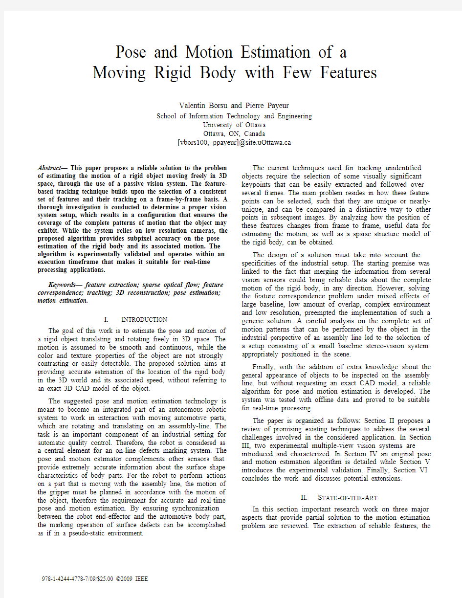
In order to reproduce the automotive body inspection scenario in the laboratory, an experimental setup has been built that uses a rigid body structure consisting of a mobile robot to generate the movement, along with a mock-up door mounted on its upper face, as shown in Fig. 1. The prototype was built with the objective of getting as close as possible to the actual set of visible features offered by a real automotive body part, in this case, a car door with a window, the door knob and a key
hole.
Figure 1. Mock-up rigid body used for experimental evaluation.
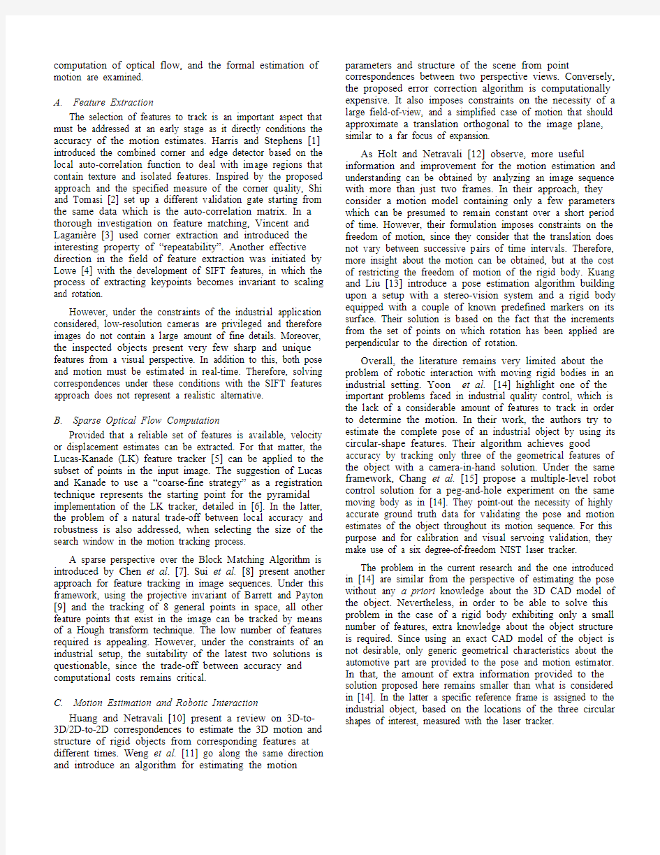
In the process of selecting the most suitable configuration for a multiple-view vision system in the context of on-line quality control, a number of settings have been evaluated. After a thorough investigation regarding the patterns of motion that the rigid body might exhibit on the assembly line, a configuration consisting of two orthogonal cameras was evaluated, as shown in Fig. 2a. One camera is positioned over the inspected part and points downward, while the second camera collects a lateral view of the moving part. Therefore, only two cameras are sufficient to extract the necessary motion information. As imposed by stereoscopic vision, the correspondence problem must be resolved in order to reconstruct the 3D position of some keypoints. Unfortunately, in this case the correspondence problem cannot be solved accurately. This is mainly because of the small number of features that can be extracted and matched from the limited
overlapping regions of the views.
Figure 2. Alternative configurations with: a) two orthogonal cameras (Cam 1 and Cam 2), and b) a single stereo-vision system (CamR and CamL).
Considering the relatively straight motion of the assembly line, the acquisition system was modified to measure the motion information with a single stereo-vision configuration located above the assembly line and pointing downward, as shown in Fig. 2b. In this configuration the world reference
frame is attached to the left camera (CamL) with the optical axis, Z , pointing down. The XY plane defines the surface of motion of the object. The motion pattern of the rigid body is mainly a translation along the X axis in the first part of the sequence, coupled with a minor translation along the Y axis in the second part of the motion sequence. The latter corresponds to a slight turn on the right w.r.t. the direction of motion. The speed of the mobile robot varies only slightly throughout the motion. Also, as the robot is manually driven by a remote control, it exhibits a low level of vibrations throughout the sequence of motion. Following experimentation, a baseline, b , of about 25cm between the two cameras was found to provide better results than the cases with closer vision sensors under the same configuration. The experimentation conducted on the mock-up model of a car door revealed that the stereo-vision configuration illustrated in Fig. 2b, with its principal axis pointing perpendicularly to the object and direction of motion, represents the most suitable acquisition strategy for estimating the pose and motion of the automotive body part moving on an assembly line. The calibrated vision system includes two Point Grey Flea2 IEEE-1394b CCD cameras with CCTV 3.5 mm lenses. Software solutions are implemented in C++ with the open-source library for computer vision, OpenCV.
Also, in order to create a set of ground truth data that will be compared to the pose and motion estimates, the trajectory of the mobile part is recorded during motion by tracing a line over a 156x140 cm grid (made of 1x1 cm squares) that was fixed on the floor. A third camera, synchronized with the calibrated vision system, provides information about the timing of the movement by detecting the position of the pencil marker over the grid during the recorded sequence. Although, not as highly accurate as the ground-truth data accumulation presented in [15], the recorded trajectory is fairly accurate and provides a good basis of comparison.
The data is recorded at a frame rate of 15fps, and 640x480 pixels of resolution. During this initial phase of experimentation the videos are recorded offline, but the application runs fast enough to operate in real-time on live video feeds. Since the rigid body is moving with slightly variable speed and because the frame-extraction rate is also imposed by the processing of the ground truth data, the frame-extraction process is triggered every time the pencil intersects with grid lines separated by 2cm. As a result, the average frame extraction frequency, f extr , is 1.5Hz. A total number of N=48 extracted frames are employed in the sequence. The total displacement of the mock-up door is about 100 cm throughout the entire sequence. The duration of the entire processed video sequence is about 40 s.
IV. P ROPOSED A LGORITHM
Building upon the last acquisition configuration detailed in Section III, an algorithm is proposed to resolve the pose and motion estimation problem. The technique offers reliable results with respect to the estimation of the pose of the object as well as for the motion it exhibits. A set of six features that can be extracted with a maximum of stability from the mock-up car door are tracked, that is the four corners of the door window and the two corners of the door knob. These keypoints are called the macro-features.
Fig. 3 presents the block-diagram of the proposed algorithm that is applied on the processed set of videos recorded with the configuration defined in Fig. 2b. Using a graphical user interface (GUI), the process is initiated by the operator who roughly selects the macro-features in the first frame that represents a full view of the inspected object in both cameras. This action (A1) is performed only once, on the frame grabbed by the right camera (camR), as an initialization step. For every chosen feature an 11x11 pixels window is defined and centered on the selected feature. A search for the exact locations of the corners (A2) is then performed only over those windows of interest to refine the estimation of the feature localization in the image. This is achieved using the Shi and Tomasi corner detector [2] with a subpixel accuracy refinement. The accurately located macro-features provide the input data to the pyramidal Lucas-Kanade tracker [6] that gives reliable information about their displacement throughout the processed sequence. Subsequently, the tracker contains a built-in validation gate for pruning away the outliers. The key elements of this procedure are the tracking error, linked to how much the neighborhood that contains each macro-feature changed during the tracking, and the norm of the optical flow in both directions with respect to the dominant norm value. Fig. 4 illustrates the sparse optical flow results for a frame captured
by the right camera.
Figure 3. Proposed pose and motion estimation algorithm.
The corner detection refinement process (A3) is reapplied
on every r frames among the set of extracted frames (i.e. N1
times during the entire sequence, with N1=N/r). This aims at
correcting for the error that might be accumulating between the
position of the features given by the tracker and the more
accurate location provided by the corner detector.
Although the LK tracker is able to compute the
displacements for all extracted corners, features that are not
part of the selected macro-features set are discarded since they
exhibit much larger variations in their position estimation over
the tracking period. For that reason, for solving the
correspondence problem, only the matches between the macro-
features are considered.
Figure 4. Sparse optical flow data and macro-features on the rigid body.
In order to avoid computationally expensive feature
matching techniques, as proposed in [3], advantage is also
taken of the short baseline between the cameras. The pyramidal
LK tracker also serves for directing the correspondence (A4).
Also, the parameter regarding the number of levels that the
image pyramid should contain can also be modified, making
the proposed algorithm suitable for stereoscopic configurations
with even larger baselines or systems in which the cameras are
slightly tilted with respect to the principal axis of the stereo-
vision sensor. The feature tracker in A4 is employed only once
during the processing of the motion sequence. But in general, it
can be applied every p frames (i.e. N2 times during the entire
processed sequence, with N2N/p). The feature tracker
provides an initial guess of the macro-features localization in
the correspondent frames.
Following a procedure similar to A1, a 12x12 pixels
window is centered over each of the macro-features returned by
the pyramidal LK tracker employed for the correspondence
problem. As the tracker is used only once, in the next cycles of
the algorithm, the positions of the windows are updated, based
on the optical flow information obtained from the tracking of
features in the correspondent frames taken with the right
camera.
The location of the macro-features given by the pyramidal
LK tracker for correspondence is being refined with the
application of the Shi and Tomasi corner extractor in the
corresponding frame of the left camera. The above mentioned
windows, which are being displaced every cycle, represent the
search regions for the corner detector. Based on the accurate
estimates for the macro-features correspondences obtained
previously, the 3D position of these keypoints is estimated with
a linear triangulation procedure [16]. The 3D points represent
the set of estimated data, to be compared with the ground truth
data obtained with the help of the validation system described
in Section III.
V.E XPERIMENTAL V ALIDATION
Fig. 5 shows a back-projection of the 3D points over the
corresponding image plane of the left camera and is used to
evaluate the accuracy of the pose estimation. As a calibrated
stereo-vision system is used, the epipolar lines can be
computed in the frames of the left camera and used to visually
inspect the location of the computed correspondences with respect to them. Experimentation demonstrated that sub-pixel accuracy is achieved on the back-projection of the estimated pose for the set containing the first four macro-features (see Fig. 5) in both directions. The last two macro-features exert subpixel accuracy on the back-projection error in the horizontal direction, and an average value of 1.5 pixels for the back-projection error in the vertical direction. As mentioned in Section III, the rigid body exhibits relatively straight and smooth motion (mainly, a translation along the X axis in the first part, coupled with a minor translation along the Y axis in the second part, w.r.t. the world reference frame as shown in
Fig. 2b).
Figure 5. Image from the left camera with back-projection of
estimated location of the six macro-features.
The analysis of the reconstructed 3D data is based on a set of two quality tests. The first quality measure is related to the comparison of our results with the knowledge available about the geometrical structure of the mock-up door. The reference data is accurately measured in the real world and compared to the corresponding computed values based on the 3D positions of the macro-features. The set of data consists of: the width between macro-features 3 and 4 (width1), as defined in Fig. 5, between features 5 and 6 (width2), and the height between macro-features 4 and 5 (height1), and between macro-features 3 and 6 (height2) of the rectangle representing the window. As well, the lateral size of the door knob (between macro-features 1 and 2) is monitored. The absolute relative error between the real and the estimated data is computed over the entire processed sequence. The values reported in Table I represent the mean of the absolute relative errors computed over the sequence, in the cases where corners are re-extracted every r=5 frames or not, as explained in Section IV. It can be observed that the data, in which the macro-features 5 and 6 are involved, is more erroneous than the measurements that include the other macro-features. This is caused by the higher back-projection error in the vertical direction associated with the last two-features. Moreover, from the perspective of the group containing the first four macro-features, the mean absolute error is inferior to 1cm, thus acceptable accuracy is achieved for a robotic marking process of deformed areas over an automotive part. Interestingly, there is no consistent improvement observed in the data when the features are monitored with corner re-extraction; only the rectangle width and the size of knob results tend to get closer to their real values.
TABLE I. Q UALITY M EASURE 1– GROUND TRUTH DATA COMPARISON
The second quality measure is related to the comparison of the pose and motion estimates with the ground-truth data recorded by tracing the trajectory of the rigid body on the grid fixed on the floor. In order to be able to compare the two different data sets, one that is measured with respect to the world reference frame (CamL) and the other one with respect to the grid, a two-step transformation procedure is employed. First, ten corner-shaped markers placed over the grid are recovered with the corner extractor. The method of Arun et al.
[17] is used to compute the transformation matrix between the world reference frame and the grid reference frame. With the use of the estimated transformation matrix, the 3D locations of the macro-features can be expressed with respect to the reference frame attached to the grid. In the second step, the displacements in X, Y and Z directions (w.r.t. the grid reference frame) between the macro-features and the tip of the pencil tracing the trajectory are estimated manually to allow a comparison of trajectories in the grid reference frame.
The validation procedure includes two comparisons for validating the accuracy of the pose and motion estimation. Fig.
6 illustrates the real and the estimated 3D trajectories of the rigid body throughout the sequence. For computing the estimated trajectory, we have applied the transformation procedure to the first macro-feature since it exhibits the smallest back-projection error throughout the sequence. For the initial part of the processed video, where the rigid body is smoothly translating along the X axis, the two trajectories are very close to each-other. In the second part (for X>40cm), a
slight divergence starts to appear between them.
Figure 6. Real and estimated 3D trajectories comparison
for the rigid body througout the motion.
The maximum value of this divergence is 3.5cm along the X axis, 2.8cm along the Y axis, and 2cm with respect to the Z axis. One of the most important causes of this error is the fact that the pencil that marks the grid is mounted on a spring which tends to slightly bias the trajectory when changing direction. The least-squares method used in computing the transformation matrix between the world reference frame and the grid reference frame, together with the manual measurements made in the second step of the transformation procedure, also introduce a small amount of error in the system.
For the second comparison the velocities along the X and Y axis are compared, between the ground-truth and the estimated data. In Fig. 7a it can be observed that the real and estimated velocities along the X axis are very close to each other. The rudimentary trajectory marking system is the cause of the spikes present in the last part of the sequence in both Fig. 7a
Corners re-extraction
Ground Truth Comparison
Width1
Error
(cm)
Width2
Error
(cm)
Height1
Error
(cm)
Height2
Error
(cm)
Size of knob
Error
(cm)
No 0.82 0.93 1.55 1.7 0.79 Yes 0.76 0.9 1.63 1.73 0.42
and 7b. Moreover, the velocity in the X direction is not constant as the part was manually moved with a mobile robot during experimentation, which resulted in slight variations around a mean value of 3cm/s. The velocity along the Y axis is very small in the first part of the trajectory and is basically caused by the merged effects of noise, imperfect orthogonality of the stereo-cameras with the horizontal surface over which the movement occurs, and the small variations during the motion. Then, in the second part of the motion sequence, the absolute value of the velocity along the Y axis increases as the rigid
body slightly turns right from the direction of motion.
Figure 7. Real and estimated velocities (cm/s) along: a) the X axis;
b) the Y axis, throughout the motion cycle.
Finally, the time performance of the entire processing per pair of frames represents approximately δp ≈0.2s which, subtracted from the average frame-extraction rate δt ≈0.667s, leaves a reserve of δr ≈0.47s until the next frame will be captured. Experimentation demonstrated that increasing the frame-extraction rate does not significantly improve the accuracy for this type of trajectory. This makes the proposed solution a valid approach for a real-time implementation, as required in an industrial setting.
VI. C ONCLUSIONS AND F UTURE W ORK
In this paper, the problem of pose and motion estimation of a rigid body exhibiting a limited number of dominant features, and moving in 3D space is addressed. The use of a calibrated stereo-vision system is evaluated in regards of industrial inspection systems requirements. An algorithm is proposed to effectively track the few features available and estimate pose and motion of the moving rigid body in real-time. The technique is validated experimentally and demonstrates that reliable results can be achieved, even when standard video cameras are used.
Future investigation will aim at further improving the accuracy of the pose and motion estimates, by taking advantage
of the remaining time available within typical acquisition frame rates. The integration of the pose and motion estimator with a robotic arm will also be performed to provide actual interaction with the moving object under visual guidance.
A CKNOWLEDGMENT
The authors acknowledge the financial support from Precarn Inc., and the collaboration of Neptec Design Group Ltd and Honda Canada to this research.
R EFERENCES
[1] C. Harris and M. Stephens, “A combined corner and edge detector,”
Proc. of the 4th Alvey Vision Conference , UK, 1988, pp. 147–151.
[2] J. Shi and C. Tomasi, “Good features to track,” Proc. of 9th IEEE Conf.
on Computer Vision and Pattern Recognition , USA, 1994, pp. 593-600. [3] E. Vincent and R. Laganière, “Matching feature points in stereo pairs: a
comparative study of some matching strategies,” in Machine Graphics & Vision , vol. X, no. 3, 2001, pp. 237–259.
[4] D. Lowe, “Distinctive image features from scale-invariant keypoints,”
Intl. Journal of Computer Vision , vol. 60, no. 2, 2004, pp.91-110.
[5] B. D. Lucas and T. Kanade, “An iterative image registration technique
with an application to stereo vision,” Proceedings of the 1981 DARPA Imaging Understanding Workshop , 1981, pp. 121-130. [6] J. –Y. Bouguet, “Pyramidal implementation of the Lucas Kanade
feature tracker – description of the algorithm,” [on-line], http://robots.stanford. edu/cs223b04/algo_tracking.pdf.
[7] Y. K. Chen, Y. T. Lin, and S. Kung, “A feature tracking algorithm using
neighborhood relaxation and multi-candidate pre-screening,” Proc. of the Intl. Conf. on Image Proc., vol. II, Switzerland, 1996, pp.513-516. [8] H. Sui, Z. Zhang, and S. Kong,“Feature tracking from an image
sequence using geometric invariants,” Proc. of the IEEE Comp. Soc. Conf. on Computer Vision and Pattern Recognition , Puerto Rico, 1997, pp. 244-249.
[9] E. Barrett and P. Payton, “General Methods for Determining Projective
Invariants in Imagery”, CVGIP:Image Underst anding , vol. 53, 1991, pp. 46-65.
[10] T. Huang and A. Netravali, “Motion and structure from feature
correspondences:A Review”, IEEE Proc., vol. 82(2), 1994, pp. 252-267. [11] J.Weng, T.Huang, and N.Ahuja,“Motion and structure from two
perspective views:Algorithms, error analysis and error estimation” IEEE Trans. on Pattern Analysis and Machine Intelligence , vol. II(5),1989, pp. 451-476.
[12] R. Holt and A. Netravali, “Number of solutions for motion and structure
from multiple frame correspondence,” International Journal of Computer Vision , vol. 23(1), 1997, Kluwer Acad. Publishers, pp. 5-15. [13] J. M. Kuang and M. Liu, “A novel explicit pose estimation algorithm
based on Euclidean geometry,” Proceedings of the 2007 Intl Conference on Information Acquisition , 2007, Korea, pp. 247-252.
[14] Y. Yoon, G. DeSouza, and A. Kak, “Real-time tracking and pose
estimation for industrial objects using geometric features,” Proc. of the IEEE Intl. Conf. on Robotics & Automation , Taiwan, 2003, pp. 3473-3478.
[15] T. Chang, T. Hong, G. Holguinm J. Park, and R. Eastman, “Dynamic
6DOF metrology for evaluating a visual servoing system”, Proc. of the 2008 Performance Metrics for Intelligent Systems (PerMIS) Workshop, 2008, USA, pp.173-180.
[16] R. Hartley and A. Zisserman, Multiple View Geometry in Computer
Vision , Cambridge University Press, Cambridge, UK, 2000.
[17] K.S. Arun, T.S. Huang, and S.D. Blostein, “Least-Squares fitting of two
3-D point set”, IEEE Transactions Pattern Analysis and Machine Intelligence ,vol.9,no.5, 1987, pp. 698-700.
商务礼仪销售员礼仪规范
(商务礼仪)销售员礼仪规 范
菏泽中富置业XX公司 售楼人员礼仪规范 一、仪态 1、以站立姿势工作的售楼人员,其正确的站立姿势应是:双脚自然靠拢,宽度不超过肩宽(体重均落于双脚上,肩平、头正、俩眼平视前方、挺胸、收腹)。双腿不能叉得太开,不能抖动。 2、以坐姿工作的售楼人员,必须坐姿端正。双腿自然平放,双膝且拢。不得跷二朗腿,不得抖动双腿,不得将腿搭于座椅扶手上,不得盘腿,不得脱鞋。 3、工作时间,身体不得东倒西歪,前倾后仰,不得伸懒腰、驼背、耸肩或趴于工作台上。 4、以站姿工作时,双手交叉自然垂放于腹前;以坐姿工作时,双手平放台面、自然下垂或放于腿上。不得叉腰、交叉胸前、插入衣裤或随意乱放,不抓痒、挖耳、抠鼻孔,不得敲桌子、敲击或玩弄其他物品。 5、行走略快,但不能跑,不得二人搭肩、挽手而行。和客人相遇应靠边走,不得从二人中间穿行。和顾客同时进出门(包括电梯门),应让顾客先行。请人让路要讲“对不起”,不得横冲直撞,粗俗无礼。 6、为客人指方向时应右手五指且拢掌心向上,以45度角向右前方伸出做指示,不得用手指或笔杆指客人或为人指方向。 7、见顾客入售楼处,应立即起立,以标准站姿迎接客人。 8、带顾客见样板房或工地现场时,所有人员均应戴安全帽。 9、双手向客人递上名片。掌心向上,拇指于上,四指于下。名
片的正面须对着客人。双手接过客人名片迅速念出客人姓名、职务等:“XX经理,XX小姐/先生。且迅速记住客人的姓名、职务,以便整个接待过程中准确称呼客人。递接名片时,应站起略向客人弯腰以示尊重。坐下时应将客人的名片按职务大小顺序排列于桌上。不得摆弄客人名片。 二、仪表 1、身体、面部、手部必须清洁,提倡每天洗澡,换内衣。 2、每天刷牙,提倡饭后刷牙,上班前不吃异味食物以保证口腔清新。 3、头发要常洗,整齐。男员工头发以发脚不盖过耳部及衣领为适度;男员工不得化妆,不准卷发,不准留胡须,头发不得有头屑;女员工头发梳理整齐,不得披头散发。男女员工头发均不得染怪异色彩。 4、女士上班要化淡妆,涂自然淡雅的口红、描眉,不得浓妆艳抹。 5、不得佩戴过多饰物,不得戴吊坠耳环,不得戴夸张的项链、戒指和手链、脚链,不得留长指甲,不得涂有色指甲油。 6、必须按公司规定佩戴工牌。 7、不得当众整理个人衣物。不得将任何物件夹于腋下。 三、表情 1、微笑,是售楼人员最起码应有的表情。销售人员对进售楼处的每壹个人员均微笑。见房途中遇同事带客户时,应和同事及同事的
排球基本动作教案
一、开始部分 10’ 1、学生按照要求排队,师生问好。 2、体育老师点名,检查上课出勤情况。 3、宣布本课的学习内容、目标和要求,安排见习生。 X X X X X 0 O O O O X X X X X 0 O O O O △ 二、准备部分 20’ 1、教师自我介绍 学生与教师相互介绍情况。 2、为学生安排体育课的队形。 根据学生身高和特点安排队形。 3、准备活动,徒手操(4×8拍) A 头部运动 B 肩部运动 C 扩胸运动 D 体转运动 E 腹背运动 F 全身运动 G 原地高抬腿跑 H 手腕关节运动 要求:活动充分。 三、基本部分 50’ 排球 排球比赛是由两队各6名队员在被网隔开的排球场内,根据规则规定,以身体的任何部位将球击入对方场区,而不使其落入本方场区的集体的、攻防对抗的体育项目。 1、首先讲解排球选项课学习的基本理论、基本技术、 2、讲解排球选项课的期末考试内容,以供学生积极训练,积极准备。 3、讲解排球技术的基本概念: 排球技术是指在排球规则允许的条件下,运动员采用的各种合理的击球动作和为完成击球动作所必不可少的与其他配合动作的总称。 4、讲解排球技术的基本组成动作: 排球的技术主要包括:准备姿势与移动、垫球、传球、发球、扣球、拦网。 5、讲解排球运动的概念:
排球运动是由参加运动的人,以身体的任何部位(以单手或双手为主)相互在空中击球,使球不落地,既可隔网进行比赛,也可不设球网进行击球游戏的一种体育运动项目。 排球球性练习: 1、6个人一个小组,每个小组一个排球,站成一个圆圈,熟悉球性练习。 2、每人自垫球5个,然后换人。 3、在圆圈内对垫球,在圆圈内对传球。 4、不要求排球动作的正确性,只要求熟悉球性。 四、结束部分 10’ 1、点名整队。 2、小结,收拾体育器材。 3、放松操。 4、师生告别。
排球垫球的动作要领
排球垫球的动作要领 垫球是排球基本技术之一。是接发球、接扣球以及后排防守的主要技术动作,是组织反攻战术的基础。垫球技术的熟练程度和运用能力,是争取胜利的重要条件。有下面双手垫球、体侧垫球、正面低姿势垫球、背垫球、单手垫球、前扑垫球、鱼跃垫球、侧卧垫球、滚翻垫球、挡球和救入网球等。其中正面双手垫球是各种垫球技术的基础,适合接速度快、弧度平、力量大、落点低的各种来球,在排球比赛中运用较多。 垫球 垫球是用小臂从球的下部,利用来球的反弹力向上击球的技术动作.它在比赛中运用于接发球,接扣球,接拦回球,有时也用来处理球.是排球基本技术之一. (一)垫球技术要领 1,正面双手垫球 正面对正来球方向,两脚开立稍宽于肩,脚跟微起,两膝弯曲稍内收的准备姿势.两手手指重叠后合掌互握,掌跟靠拢.两拇指平行朝前,手臂伸直,手腕下压,两臂外翻,前臂形成一个击球平面。击球点在腹前约一臂距离,用前臂腕关节以上10厘米左右,桡骨内侧平面触球。击球时,手臂插入球下,蹬腿抬臂,身体重心向前上方移动。同时含胸,压腕,顶肘等动作协调配合,身体和两臂要有自然的随球伴送动作,以便控制球的落点和方向. 2,体侧双手垫球 当球向左侧飞来,右前脚掌内侧蹬地,左脚向左跨出一步,左膝弯曲,重心随即移至左脚上,两臂夹紧向左伸出,右肩稍向下 倾斜,用向右转腰和提左肩的动作,使两臂击球面截住球的飞行路线,垫击球的后下部。 3,背垫球 判断好球的飞行方向,迅速移动到球的落点处,背对击球方向,两臂夹紧伸直,击球手形与正面垫球相同,击球点要高于肩部。击球用力是通过抬头挺胸,展腹后仰,带动手臂向后上方抬送而实现的.在背垫低球时,也可以屈肘,翘手腕动作,以虎口处将球向后上方垫起. 4,单手垫球 单手垫球多在无法用双手垫球的情况下采用.体侧单手垫球方法是一脚迅速向侧前方跨出一大步,重心移至跨出的腿上,以跨出腿的同侧臂迅速伸出,用虎口或小臂击球的后下部。在体前可用手背平面击球,手臂要伸直,有抬击动作. (二)垫球技术练习方法 1,在简单条件下掌握垫球技术 (1)原地做徒手模仿垫球动作练习. (2)垫固定球.两人一组,一人持球于腹前,另一人用 垫球动作击球,体会垫球部位和用力动作.要求蹬腿抬臂协调用力. (3)自垫球.一人一球连续向上自垫,垫球高度可固定,也可高,低结合. (4)抛垫球.两人一球相距4~5米,一人将球抛至同伴的腹前,同伴将球垫回. (5)移动垫球.两人一组,一人抛出不同距离,方向,速度和高度的球,另一人在移动中采取正面,侧面,跨步,低姿或背向等法将球垫回. (6)对垫球.两人相距4~5米,做连续对垫球练习,尽量采用正面垫球. (7)对墙连续垫球.要求手臂角度固定,全身协调用力. (8)转换方向垫球.三人一组,三角连续垫球.可任意或按顺时针,逆时针的方向依次
《排球——正面垫球》教学设计
《排球——正面垫球》教学设计 银川市第十五中学刘建华 一、指导思想 本课依据《体育课程标准》的理念,以“健康第一”为指导思想,以学生发展为中心,突出体现学生学练的主体地位,不断激发学生的学习兴趣,提高学生学练的基本技术和技能。本节课就是要体现体育运动本质就是游戏活动这一认识,游戏贯穿课的首尾,游戏活动替代热身准备和整理放松活动。本节课教学的主旨是:教师努力成为一位体验课堂活动的“学生”,而学生成为课堂的“驱动器”和“发动机”。教师不但要充分参与到各种互动活动之中,要同学生一起学练和游戏,而且要在潜移默化中让学生在知、情、意、行方面有所体会和收获。 教学过程遵循由易到难,由浅到深,层层递进的教学原则,教学内容和手段的安排要具有目的性和针对性。教学中教师要注重启发学生自学、自练、合作和探究学习;注重发展学生的合作意识和社会适应能力;逐步让学生形成积极的学习态度。 二、教学内容 排球:双手正面垫球 三、学情分析 1.教学内容分析 通过总结以往教学,可以看出排球是学生普遍喜欢运动内容,特别是围圈垫球和场地练习是学生最喜欢练习形式。学生喜欢打排球,这给排球基本技术教学提供了契机。如何通过排球基本技术的教学,使学生打排球的兴趣、爱好和行动最大化是教学中首要设计和考虑的。 2.学生情况分析 (1)对于八年级初学的学生来说,排球又重又硬,球打在手臂上很疼,而且出现红肿的情况,特别是女学生在练习中因为怕疼,而畏缩或不愿意练习的情况比较普遍。 一是教师要主动的引导和教育学生,把注意力放在学习上,教师要帮助学生,让学生在练习中有所提高和进步;同时教师要鼓励学生不怕困难,培养学生要有吃苦精神。二是教师要帮助学生快速进步,让学生体会到付出带来的快乐,尤其是一对一对垫时,教师要多多鼓励和表扬学生,激发他们练习的热情。 (2)学生“愿意”不受约束的“野玩”排球,但是在学习排球技术动作时
服务礼仪标准
网点服务礼仪标准 第一节通用服务礼仪标准 通用服务礼仪是指网点内各个岗位人员共同遵循的礼仪标准,也是服务行业从业人员面对客户时应遵守的基本礼仪标准,具体包括:仪容仪表、形体仪态、表情神态、沟通语言、接待礼仪、电话礼仪、会议礼仪、社交礼仪。 一、仪容仪表 仪容是个人仪表的重要组成部分,由发式、面容以及人体所有未被服饰遮掩的肌肤(如手部、颈部)等内容构成。仪表是一种无声的语言,显示着一个人的个性、身份、素养、及其心理状态。在服务中,得体的妆容和着装会体现个人良好的职业气质,给客户留下深刻的印象,从而提升客户对农行企业形象的认知。 (一)男士 1.仪容 (1)发式:头发需勤洗,无头皮屑,且梳理整齐;不染发,不光头,不留长发;以前不掩额、侧不盖耳、后不触衣领为宜。 (2)面容:忌留胡须,养成每天修面剃须的良好习惯;面部保持清洁,眼角不可留有分泌物,如戴眼镜,应保持镜片的清洁;保持鼻孔清洁,平视时鼻毛不得露于孔外。 (3)口腔:保持口腔清洁,不留异味,不饮酒或含有酒精的饮料。 (4)耳部:耳廓、耳跟后及耳孔边应每日清洗,不可留有皮屑及污垢。 (5)手部:保持手部的清洁,养成勤洗手勤剪指甲的良好习惯,指甲不得长于1mm。 (6)体味:勤换内外衣物,给人清新的感觉。 2.仪表 (1)西装:着统一制服、领带,干净平整,无污渍、无破损;西裤裤脚长度以穿鞋后距地面1cm为宜。 (2)衬衫:着长袖衬衫,衬衫袖口须扣上,长度应超出西装袖口1cm为宜;衬衫下摆须掖在裤内。 (3)领带:领带应紧贴衬衫领口正中,长度以在皮带扣上下缘之间为宜。 (4)领带夹:夹在衬衫的第四和第五粒扣子之间。 (5)工号牌:在营业厅内须佩戴工号牌,别针式工号牌要端正地别在左胸前,挂牌式工号牌要正面朝外。 (6)袜子:着深色薄棉袜,如黑色、深蓝、深灰色袜等。 (7)鞋子:着黑色、系带、牛皮皮鞋,光亮无尘。 (8)饰物:手腕部除手表外不得戴有其他装饰物,手指不能佩戴造型奇异的戒指,佩戴数量不超过一枚。 (二)女士 1.仪容 (1)发式:头发需勤洗,无头皮屑,不染发,且梳理整齐;长发需挽起并用统一的头饰固定在脑勺后;短发要合拢在耳后。 (2)面容:面部保持清洁,眼角不可留有分泌物,保持鼻孔清洁。工作时要化淡
公司员工礼仪规范
公司员工礼仪规范 公司为进一步规范及完善服务标准,树立良好企业形象,特制订本规范,本规范共五部分,分别为: 一、仪容仪表礼仪 适用范围:公司全体员工 二、日常业务中的礼仪 适用范围:公司全体员工 三、前台接待礼仪 适用范围:前台、接待人员 四、商务礼仪 适用范围:公司职员、销售部员工 本规范内容于签发之日起生效,要求全体员工遵照执行! 具体内容详述如下:
一、仪容仪表礼仪 第一条职员必须仪表端庄、整洁。具体要求是: 一、对男员工的要求 1、发型要求: 干净整洁 不宜过长,最短标准不得剔光头 前部头发不遮住自己的眉毛 侧部头发不盖住自己的耳朵 不能留过长、过厚的鬓角 后面的头发不超过衬衣领子的上部 2、面部修饰 剔须修面,保持清洁。 商务活动中会接触烟、酒等有刺激性气味的物品,要保持口气清新。 3.胡子:胡子不能太长,应经常修剪。 4.口腔:保持清洁,上班前不能喝酒或吃有异味食品。 二、对女员工的要求 1、发型要求: 时尚得体,美观大方、符合身份。 发卡式样庄重大方,以少为宜。 2、面部修饰: 女士化妆是自尊自爱的表现,也是对别人的一种尊重,是企业管理完善的一个标志。要求化淡妆,保持清新自然,化妆注意事项: 化妆要自然,力求妆成有似无 化妆要美化,不能化另类妆 化妆应避人 3、指甲:指甲不能太长,应经常注意修剪。女性职员涂指甲油要尽量用淡色。 4、女性职员化妆应给人清洁健康的印象,不能浓妆艳抹,不宜用香味浓烈的香水。
第二条工作场所的服装员工服装的要求 1.女性职员要保持服装淡雅得体,不得过分华丽。 2.职员工作时不宜穿大衣或过分雍肿的服装;不穿无领、无袖、领口较低或太紧身的衣服。 3.男士不着印有大花、大方格的衬衫,女士不穿露、透、短的衣服,不穿背心、短裤、拖鞋,不能赤脚穿鞋。鞋子应保持清洁,如有破损应及时修补,不得穿带钉子的鞋。 4.职员或员工进入生产区、库房、实验室等区域应着工作服。 第三条在公司内员工姿势和动作的要求 1.站姿:两脚脚跟着地,脚尖离开约45度,腰背挺直,胸膛自然,颈脖伸直,头微向下,使人看清你的面孔。两臂自然,不耸肩,身体重心在两脚中间;会见客户或出席仪式站立场合,或在长辈、上级面前,不得把手交叉抱在胸前。2.坐姿:坐下后,应尽量坐端正,把双腿平行放好,不得傲慢地把腿向前伸或向后伸,或俯视前方。 3.公司内与同事相遇应点头行礼表示致意。 4.握手时用普通站姿,并目视对方眼睛。握手时脊背要挺直,不弯腰低头,要大方热情,不卑不亢。伸手时同性间应先向地位低或年纪轻的,异性间应先向男方伸手。 5.出入办公室的礼貌:进入办公室,要先轻轻敲门,听到应答再进。进入后,回手关门,不能大力、粗暴。进入办公室后,如对方正在讲话,要稍等静候,不要中途插话,如有急事要打断说话,也要看住机会。而且要说:"对不起,打断您们的谈话"。 6.递交物件时,如递文件等,要把正面、文字对着对方的方向递上去,如是钢笔,要把笔尖向自己,使对方容易接着;至于刀子或剪刀等利器,应把刀尖向着自己。 7.走通道、走廊时要放轻脚步。 8.无论在自己的公司,还是去访问的其他公司,在通道和走廊里不能一边走一
排球基本动作教案
一、开始部分10’ 1、学生按照要求排队,师生问好。 2、体育老师点名,检查上课出勤情况。 3、宣布本课的学习内容、目标和要求,安排见习生。 X X X X X 0 O O O O X X X X X 0 O O O O △ … 二、准备部分20’ 1、教师自我介绍 学生与教师相互介绍情况。 2、为学生安排体育课的队形。 根据学生身高和特点安排队形。 3、准备活动,徒手操(4×8拍) A 头部运动 B 肩部运动 C 扩胸运动 D 体转运动 E 腹背运动 F 全身运动 % G 原地高抬腿跑H 手腕关节运动 要求:活动充分。 三、基本部分50’ 排球 排球比赛是由两队各6名队员在被网隔开的排球场内,根据规则规定,以身体的任何部位将球击入对方场区,而不使其落入本方场区的集体的、攻防对抗的体育项目。
1、首先讲解排球选项课学习的基本理论、基本技术、 2、讲解排球选项课的期末考试内容,以供学生积极训练,积极准备。 . 3、讲解排球技术的基本概念: 排球技术是指在排球规则允许的条件下,运动员采用的各种合理的击球动作和为完成击球动作所必不可少的与其他配合动作的总称。 4、讲解排球技术的基本组成动作: 排球的技术主要包括:准备姿势与移动、垫球、传球、发球、扣球、拦网。5、讲解排球运动的概念: 排球运动是由参加运动的人,以身体的任何部位(以单手或双手为主)相互在空中击球,使球不落地,既可隔网进行比赛,也可不设球网进行击球游戏的一种体育运动项目。 排球球性练习: 1、6个人一个小组,每个小组一个排球,站成一个圆圈,熟悉球性练习。 . 2、每人自垫球5个,然后换人。 3、在圆圈内对垫球,在圆圈内对传球。 4、不要求排球动作的正确性,只要求熟悉球性。 四、结束部分10’ 1、点名整队。 2、小结,收拾体育器材。 3、放松操。 4、师生告别。
办公室基本礼仪标准
办公室基本礼仪标准 一、目的 为了加强办公室正规化管理,规范员工日常行为,提高员工个人职业形象,塑造良好的企业形象,制定本标准制度。 二、适用范围 适用于XX有限公司所有员工。 三、办公室基本礼仪的定义 办公室是一个处理公司业务的场所,办公室的礼仪不仅是对同事的尊重和对公司文化的认同,更重要的是每个人为人处事,礼貌待人的最直接表现。 四、办公室的日常基本礼仪 (一)创造满意的工作场所 办公室是企业的门面,是来访者对企业的第一印象。 1.办公室应保持整洁。桌面只放些必要的办公用品,且摆放整齐。 2.办公室应给人以高效、宁静的印象。 3.室内应经常通风换气。 4.办公室一般不要摆放私人照片及悬挂明星或美女挂历。 (二)办公室的职场形象与人际关系 办公室的人员是一个集体,无论是对单位还是外来人员,都应体现一个集体的每个成员对他人、对社会的尊重和责任心。 1.个人形象 1)仪表端庄、大方; 2)举止要庄重、文雅; 3)说话要文明,有分寸; 4)遵守公共道德和行为准则。 2.人际关系 1)与领导相处的原则 a)与领导相处应心存敬意,注意维护领导的形象。 b)与领导相处,应遵守必要的礼节。 2)与同事相处的原则 a)与同事相处应以礼相待、彼此尊重。 b)与同事相处应保持适当的距离
c)与同事相处应树立容纳意识,敢于承担责任。 (三)言行举止行为规范 1.语言行为规范 1)每天主动、快乐地向同事打招呼;您的微笑将为轻松的工作气氛贡献力量。 2)注重语言文明规范,不得讲粗话、脏话。办公区域内不得大声喧哗。语言尽量 做到准确、亲切、生动、语速适中,语量适度,吐词清楚,用词适当,态度温 和。 3)应注意语言习惯,无论对上级、对同事、对下级、对客户都应养成使用“请、 您好、谢谢、不客气、对不起”等文明礼貌用语习惯。 4)应注意语言技巧,尽量使用请求式语言,不说有伤他人自尊心或人格的话,尽 量避免命令式语言,少用否定式语言,说话要注意察言观色,拒绝他人时要尽 量委婉。 2.行为举止规范 1)公司人员每日上班须按要求着装和佩戴工作牌。 2)在办公区域要精神饱满,不打瞌睡。坐立要端正,不准有坐在桌面上、脚放在 桌面上等不雅观的行为。站立时身子不宜歪斜,更不宜斜靠在其他物体上。 3)办公场所要保持环境清洁,不随地吐痰、乱丢废弃物,办公用品摆放整齐。 4)离开办公室办事应主动向同事打招呼说明事由及离开时间。 3.基本姿势规范 1)坐姿: a)腰脊挺直,不要靠到椅子背上, b)两肘并拢; c)两腿并拢; d)两手叠放在两腿之间。 (四)办公室环境礼仪 1.不可在公共办公区吸烟、扎堆聊天、大声喧哗。 2.节约水电,禁止在办公家具和公共设施上乱写、乱画、乱贴,保持卫生间清洁。 3.饮水时,如不是接待来宾,应使用个人的水杯,减少一次性水杯的浪费。不得擅 自带外来人员进入办公区,会谈和接待安排在洽谈区域。 4.最后离开办公室的人员应关电灯、门窗、及室内总闸。个人办公区要保持办公桌 位清洁,非办公用品不外露,桌面摆放整齐。 5.有事离开自己的办公座位时,应将座椅推回办公桌内。 6.下班离开办公室前,使用人应该关闭所用机器的电源,将台面的物品归位,鎖好贵
2017中考体育排球垫球技术讲解
蒲城中考体育排球垫球技术讲解 一.垫排球定义:垫球是排球运动的基本技术之一,是利用手臂从球的下部向上击球的技术动作。 二.垫排球正确动作讲解事项: 垫球手型:一般有三种。 一为抱拳式:双手抱拳互握,两拇指平行向前; 二为叠掌式:两手掌根紧靠,两手手指重叠后合掌互握,两拇指平行, 三为互靠式:两手腕部紧靠,两手自然放松。 无论什么手型,都应注意手腕下压,两臂外翻形成一个平面。 准备姿势:两腿前后开立,左右脚间距离与肩同宽,两手自然持球. 向上抛球:抛球出手时,尽可能使球向自己的正上方行进.与此同时,把要击球的手上动作做好,准备击球 准备击球姿势:中心降低,双腿微屈,与此同时,把要击球的手上动作做好,准备击球 击球动作::重心抬高,两臂夹紧伸直,两脚向正上方蹬地并抬臂,同时压腕顶肘. 三.分解动作,单个动作讲解.: 准备击球姿势:
1.手臂动作:将球抛出之后,两手迅速做出垫球手型,且两臂夹紧伸直, 2.双腿屈膝:将球抛出之后,身体重心迅速降低,同时把手臂动作做好. 辅助动作练习:空手做准备击球姿势 击球动作: 1.击球部位:正面双手垫球的击球点一般应保持在腹前一臂远距离,用小臂前半部腕关节以上左右挠骨内侧平面去击球。垫击部位过高或过低,不便垫准和垫稳,并且还容易造成“持球”“连击”犯规或垫球失误等。同时,击球点保持在腹前,便于控制手臂与地面的角度;便于观察来球;便于运用身体的协调力量,可以提高垫球的准确性。对墙练习击球 2.击球动作:重心抬高,两臂夹紧伸直,两脚向正上方蹬地并抬臂,同时压腕顶肘. 空手练习击球动作 击球时用力::垫球时根据落球力量、速度和垫击的距离,掌握好手臂迎击球的用力和缓冲作用。如落球速度慢或垫击球的距离较远时,垫击用力大些,必须加大抬臂击球动作,来增加球的反弹力;如落球速度快或垫击距离较近,垫击时,可用力小些,靠球的反弹力量将球垫起;如落球速度大,为了缓冲来球力量, 错误一:屈臂 屈臂是指在击球的瞬间,利用屈肘关节,抬前臂的力量来击球。
排球垫球的动作要领
排球垫球的动作要领 的主要技术动作,是组织反攻战术的基础。垫球技术的熟练水准和使用水平,是争取胜利的重要条件。有下面双手垫球、体侧垫球、正面低姿势垫球、背垫球、单手垫球、前扑垫球、鱼跃垫球、侧卧垫球、滚翻垫球、挡球和救入网球等。其中正面双手垫球是各种垫球技术的基础,适合接速度快、弧度平、力量大、落点低的各种来球,在排球比赛中使用较多。 垫球 垫球是用小臂从球的下部,利用来球的反弹力向上击球的技术 动作.它在比赛中使用于接发球,接扣球, 接拦回球,有时也用来处 理球.是排球基本技术之一. (一)垫球技术要领 1,正面双手垫球 正面对正来球方向,两脚开立稍宽于肩,脚跟微起,两膝弯曲稍内 收的准备姿势.两手手指重叠后合掌互握,掌跟靠拢.两拇指平行 朝前,手臂伸直,手腕下压,两臂外翻,前臂形成一个击球平面。击球点在腹前约一臂距离,用前臂腕关节以上10 厘米左右,桡骨内侧 平面触球。击球时,手臂插入球下,蹬腿抬臂,身体重心向前上方移 动。同时含胸,压腕,顶肘等动作协调配合,身体和两臂要有自然的 随球伴送动作,以便控制球的落点和方向. 2,体侧双手垫球 当球向左侧飞来, 右前脚掌内侧蹬地,左脚向左跨出 ,左膝弯 曲,重心随即移至左脚上,两臂夹紧向左伸出,右肩稍向下
倾斜,用向右转腰和提左肩的动作,使两臂击球面截住球的飞行路线,垫击球的后下部。 3,背垫球 判断好球的飞行方向,迅速移动到球的落点处,背对击球方向,两 臂夹紧伸直,击球手形与正面垫球相同,击球点要高于肩部。击球 用力是通过抬头挺胸,展腹后仰,带动手臂向后上方抬送而实现的 在背垫低球时,也能够屈肘,翘手腕动作, 以虎口处将球向后上方 垫起. 4,单手垫球 单手垫球多在无法用双手垫球的情况下采用.体侧单手垫球方法 是一脚迅速向侧前方跨出一大步,重心移至跨出的腿上,以跨出腿 的同侧臂迅速伸出,用虎口或小臂击球的后下部。在体前可用手 背平面击球,手臂要伸直,有抬击动作. (二)垫球技术练习方法1,在简单条件下掌握垫球技术 (1)原地做徒手模仿垫球动作练习. (2)垫固定球.两人一组,一人持球于腹前,另一人用 垫球动作击球,体会垫球部位和用力动作.要求蹬腿抬臂协调用力. (3)自垫球.一人一球连续向上自垫,垫球高度可固定,也可高,低结合. (4)抛垫球?两人一球相距4?5米,一人将球抛至同伴的腹前,同伴将球垫回. (5)移动垫球.两人一组,一人抛出不同距离,方向,速度和高度的
排球正面双手垫球
排球正面双手垫球是指双手在腹前垫击来球的一种垫球方法,它是各种垫球技术中最基础最简单的技术。排球正面双手垫球适合于接发各种球、扣球、拦网球等,有时也能够垫传球,在困难的时候用来组织进攻。正面双手垫球的基本手形有:抱拳式、叠掌式和互靠式等。 排球正面双手垫球技术要领 一、动作要领: 准备姿势:正面对准球,两脚开立(左右、前后)稍宽于肩,脚尖内收或朝前,脚跟稍提起,两膝弯曲稍内扣,上体稍前倾,重心靠前,落于前脚掌, 两臂微屈置于肤前,两肘稍向内收,两眼注视来球。 二、垫击手型: 抱拳式:一手半握拳,另一手抱住握拳手,两拇指平行朝前。 叠掌式:两手手指上下相叠,掌根紧靠,合掌互握,两拇指朝前。 垫击球时两臂自然伸直,两掌跟和两小臂外旋紧靠,手腕下压,使腕关节 以上的前臂形成一个垫击的平面。 用腕关节以上10厘米左右,桡骨内侧平面触球的后中下部。 四、动作要点: 正面对准来球,两脚开立,两臂并靠并插入球下,在腰腹前约一臂距离的 位置上,用腕关节以上10厘米左右部位,触球的后中下部,并迅速蹬伸前移 重心。击球时,两臂伸直夹紧,提肩压腕、前送,靠上下肢的协调用力配合 来控制击球的力量和方向。 五、易犯错误纠正: 1.击球时机的掌握:学生在练习的过程中经常出现这种情况,对球的落点 判断不好,会出现击球过早或过晚这样那样的情况,对高球的处理尤其明显, 在这其中会出现击球“落空”的现象。 2.击球部位不准确:主要是手的部位不准确。触球时,应用前臂腕关节以 上10厘米左右的桡骨内侧平面接球。如触球部位过高,两臂间隙大而不好控 制球,触球部位过低,垫球腕部不易垫稳。 3.挥臂发力不协调:挥臂发力是指接球时,以肩关节为轴心,有下而上挥 双臂击球,垫球时应配合蹬地、跟腰动作,使重心向前上方移动,手臂应适
《服务礼仪》课程标准
《服务礼仪》课程标准 一、课程的基本情况 课程名称: 《服务礼仪》 课程性质:必修 课程学时:64 适用专业:轨道交通运输(客运) 二、教学目标 通过本课程的学习,学生在知识和能力方面应达到: 1、了解礼仪的基本概念和重要性;了解东西方礼仪的差异。 2、在个人礼仪方面,掌握日常行为、服饰、仪容、仪态等礼仪标准。 3、了解商务、学校、家庭、餐饮、涉外礼仪的标准。 4、掌握轨道交通客运服务规范和礼仪;要求既掌握服务礼仪的基本理论,又要达到规范要求。 5、培养礼仪意识的修养;陶冶尊敬他人的情感;锻炼履行礼仪的意志;养成遵从礼仪的行为。 三、教学内容与要求 课题一礼仪概述 基本要求: 1、了解礼仪的基本内容及礼仪的起源与发展的历史过程,认识礼仪的特征和原则,理解礼仪的深刻内涵和作用。 2、建立礼仪意识,养成良好的文明礼貌习惯,提高自身修养,自觉遵守公共场合的礼仪规范。 3、能运用礼仪自身协调人际关系,塑造自身良好的形象。 4、掌握轨道交通客运服务的特点及服务礼仪的重要性。 重点: 1、礼仪的含义、起源及发展,礼仪的功能和作用。 2、轨道交通客运服务的特点及服务礼仪的重要性。 难点:礼仪的内涵与作用。 课题二个人礼仪 基本要求: 1、掌握站姿、坐姿、蹲姿、行姿、手姿、表情等基本礼仪。 2、掌握仪容清洁、修饰的方法。 3、掌握着装原则和配色技巧等知识;注重服饰的规范性。 4、具有讲究个人礼仪的能力,在各种场合下都能做到言谈举止非常得体,穿衣打扮非常合适。 重点: 1、面部仪容、静态仪容。 2、着装原则、姿态禁忌。
难点:个人礼仪能力的锻炼。 课题三日常交往礼仪 基本要求: 1、了解并掌握在日常交往中称呼、会面、介绍、拜访和接待、接打电话的礼仪知识。 2、了解并掌握沟通用语与礼节。 重点:沟通用语与礼节。 难点:规避礼貌禁语。 课题四商务礼仪 基本要求: 1、了解商务拜访和接待的基本礼仪,熟悉展览会、赞助会、发布会的基本程序。 2、了解商务礼仪的概念和基本原则、会议和仪式的概念、乘坐轿车的座次礼仪。 3、能熟练得体的接打商务电话,能正确书写简单的商务信函和请柬,能够布置各种会议会场及合理安排座次,能够辅助策划各种庆典仪式。 重点: 1、商务拜访和接待的基本礼仪。 2、布置各种会议会场及合理安排座次。 难点:庆典仪式的辅助策划。 课题五学校礼仪 基本要求: 1、掌握学生礼仪、校园礼仪、求职礼仪的具体内容、行为规范和注意事项。 2、掌握修饰打扮、待人接物、撰写自荐信等方面的技能。 重点:1、校园礼仪、求职礼仪的具体内容、行为规范和注意事项。。 难点:撰写自荐信。 课题六家庭礼仪 基本要求: 1、掌握家庭礼仪的概念和基本原则。 2、掌握家庭称谓礼仪。 重点:熟练运用家庭中的称谓礼仪。 难点:改善和优化家庭关系与亲友和邻里的关系。 课题七餐饮礼仪 基本要求: 掌握宴请礼仪、中餐礼仪、西餐礼仪的具体内容。 重点:宴请礼仪。 难点:西餐礼仪。 课题八涉外礼仪 基本要求: 1、了解国际交往中礼仪中的礼则、鸣炮、国旗悬挂等基本常识。 2、了解涉外活动中迎送、会见、会谈、签字等礼仪规范的仪式和程序。 重点:涉外活动中的礼仪规范。 课题九车站服务礼仪 基本要求:
公司规定礼仪姿势标准
公司规定礼仪姿势标准 所谓服务的礼仪姿势标准是对服务人员在工作中的行为、动作方面的具体要求。作为一名合格的服务人员必须做到仪容仪表、言行举止、礼仪礼貌的标准。微笑、站姿、坐姿、走姿、手势、列队姿。 1>微笑 1. 1、平视前方,目光柔和。 1. 2、肌肉放松,嘴角两端向上略微提起,面含笑意,要求微笑发自内心,发 自肺腑,无任何做作之态,口里可念着普通话的“一”字音,露出的牙齿 数规定在6到8颗。 2>站姿: 1、抬头、挺胸、肩平、两眼平视 2、重心垂直向下,防止重心偏左、偏右 3、双肩水平放松,自然下垂,腹部稍向内收缩 4、男:双手放在背后交叉,左右手相握。脚成“八”字型。 5、女:双手放在腹部交叉,左右手相握。脚成“V”字型。 3>坐姿: 1、坐要正直,不前俯后仰 2、不摆腿翘脚 3、不把脚放在扶手上 4、不可抖腿 4>走姿:1、以站立的姿势为基础,以腰部用力,使身体保持正直 2、行走时的路线是正对目标或前方形成直线 3、行走时轻快而有节奏,不可弯腰、摇头、晃肩 4、双手自然在体侧摆动,不可插入口袋 5>指引手势 1、应掌心向上,四指并拢,大拇指张开,以肘关节为轴,前臂自然上抬伸直。 2、指示方向时上体稍向前倾,面带微笑,自己的眼睛看着目标方向并兼顾对方是否意会到。 3、要注意其力度的大小、速度快慢及时间的长短。 6>例队姿:自觉按高矮顺序按站姿站好。向右看齐。
微笑标准
站姿标准 公司标准礼貌用语 1、公司统一称呼:贵宾! 2、礼貌用语:请字当头、谢不离口。 3、服务中的十个字礼貌用语:您好、请、谢谢、对不起、再见。 4、服务中的五声:客来有欢迎声、客走有欢送声、麻烦客人有致谢 声、打扰客人有致歉声、客人问时有答声。
排球双手正面垫球教案
排球教案 课次:第1课学校; ***** 教师:*** 初二年级学生:(30)人 教学目标1、认知目标:了解垫球在排球运动中的作用,并能领会双手正面垫球技术要领。 2、技能目标:初步学会双手正面垫球技术,发展协调、灵敏力量等身体素质 3、情感目标:通过排球学习,培养学生的判断能力、应变能力,以及团结协助配合的集体主义精神。 学习 内容 学习双手正面垫球 重点难点重点:手臂伸直、夹紧、击球部位难点:协调用力,插、压、蹬、送 顺序时 间 学习目标教学内容教师活动学生活动 负 荷 准 备部分15 1、快、静、齐 队形整齐,使 学生精神饱 满。 动作准确有 力。 3、使学生充分 热身,预防运 动受伤。 一、上课: 1、集合、整队,报告人 数。 2、师生问好。 3、宣布本课教学内容和 目标。 检查服装,安排见习生。 二、慢跑热身 三、徒手体操 1、头部运动 2、扩胸运动 3、肩部运动 4、腰部运动 5、膝部运动 6、正压腿 7、侧压腿 8、踝腕运动 四、专门性活动 要求: 一、简洁、明确、语 气和蔼宣布教学内 容。 安排见习生。 二、徒手体操 1、口令指挥 2、动作示范 教师统一指挥 教师评价 集合队形: ★ ●●●●●● ●●●●●● ●●●●●● ●●●●●● ●●●●●● 成体操队形: ★ ●●●●●● ●●●●●● ●●●●●● ●●●●●● ●●●●●● 小
基本 部分22 1、课堂气氛活 跃,学生认真 学习新的内 容。 2、熟悉和掌握 双手正面垫球 的准备姿势, 大部分学生掌 握垫球的基本 动作。 3、初步了解双 手正面垫球在 排球运动中的 重要性,提高 学生的学习兴 趣。 学习双手正面垫球 动作要点: 1、腕关节以上10厘米处 击球。 2、半蹲准备姿势和身体 的快速移动。 3、击球时两手臂伸直夹 紧,提肩,前伸至球下。 4、上下肢协调用力。 游戏:垫球比赛 一、教学方式: 1、教师讲解、示范。 2、组织学生做徒手练 习。 3、检查学生身体姿 势。 4、组织学生定位击球 练习。 4、组织学生做垫球练 习。 5、检查指导学生练 习。 二、教学要求: 1、认真练习、互帮、 互学。 2、技术动作合理,协 调用力。 一、练习方法: 1、集体模仿练习3—4分钟。 要求:听口令指挥。 2、垫固定球。 要求:连续10次。 3、一抛一垫。(10次) 要求: 1、距离3到4米。 2、体会移动,击球时机。 3、落点控制好。 二、教学评价。 1、技术动作合理,协调用力, 落点控制好。 2、认真练习,体会动作 中 结 束部分5 一、整队集合。 二、放松练习。 三、总结上课 情况。 四、布置作业。 五、下课。 1、教师讲解、示范。 2、 带领学生做放松练习。3、 教师讲评。 体操队形。要求:1、 集体模仿练习。2、动 作放松。3、收器材。 要求:集体模仿练习。 强调动作放松。 消除疲劳 小 场地、器材排球场、排球若干预计平均心率:130-135% 预计练习密度:45%
服务礼仪姿态标准
服务礼仪姿态标准 (服务行业=礼貌行业“100-1=0”公式) 1、见客人打招呼: 站“丁”字步→右手上胸口→左手下后背→45°弯腰鞠躬 上午好/中午好/下午好/晚上好,欢迎光临××,我是×× 2、电梯里: 手扶电梯门,让客人先进,帮客人按好电梯楼层,说:××小姐,您慢走/再见 3、帮客人指引 站“丁”字步→右手上胸口→左手下后背→45°弯腰鞠躬(打招呼)→左手背后→右手呈90°挥出去(眼神随之移动)告诉她…… (只限特殊情况/短距离,最好亲自代) 4、坐姿 坐椅子的1/3,收腹挺胸,抬头,两眼平视,双脚呈“v”字形,膝和后脚跟要靠紧 5、坐次: 以右为上,内高于外,面门为上,举重为上,远门为上,前排为上 6、同顾客交谈时: 不可晃动身体、转笔头、弄头发等小动作 ①注意面部表情,不可过分夸张 ②肢体语言适时,得体 ③发音要清晰、明朗,切记吞吞吐吐,语速不可过快 ④发出的声音不许符合当时的气氛 ⑤话题不可过于敏感(多收集客人感兴趣的资讯) ⑥满足客户的优越感,附和她的话题(但是谨记我们才是最专业的) ⑦有第三者在场,避免谈论推销话题 与客人交谈时目光注视点: 已婚女性:注视对方的嘴巴 未婚女性:注视对方的下巴,可扩大至对方的耳朵,领结附近 (聆听时将自己的视线放在对方一只眼睛中,使对方产生柔和情感) 男性:视性的焦点放在对方的鼻子附近 客人交往的常规距离: 1、熟悉客人,小于半米 2、常规距离,半米-1米之间 3、礼仪距离(尊重的距离,对长辈,对领导),1米-1米半之间 微笑与眼神训练的方法:
1、自制一个靶环牌,用时可挂在墙上或门上,身体距它2-3米,目光先投向靶 的外环,逐渐向内环移动,最后把目光集中在靶心圆上(圆点不宜画得太大)这时目光是集中的,眼睛是明亮有神的。 2、家中的摆钟,可以在距钟3-5米处坐定或站定,头与颈不动,只把目光集中 在摆心一点处,并随其摆动而追视不舍。 3、扫描法: 在室内两侧墙壁相同水平高度(以自己眼睛的高度为宜)各取一点,并做一个记号,站定在两点连线后面2-3米处,使颈部轻度左右摆动,而目光始终分别落在墙上那两个点上(这是训练眼神的简单方法) 4、对视法: 找一位与自己身高一样的同事进行互视,尽量不眨眼,直至掉眼泪 美容师 做任何事情请字当头,谢字收尾,语言得体,笑脸相迎,举止谦虚,态度和蔼 服务意识:在开展服务过程中不断的接受上司业务技能的培训及自我进修后在服务过程中不断体现出的服务预知性。 服务要求:主动、热情、耐心、周到 服务工作中五声:迎声、问候声、送声、抱歉声、谢声 工作中不可说的:藐视、斗气语、烦躁语、否定语 接电话的准备工作:早上上班前检查电话有无问题,准备纸、笔 接电话时坐姿端正,3声内接起 先问候:您好/早上好/中午好/下午好/节日要说节日快乐 + 部门:店名/美容部/休息间/调配间 + 名称:自报姓名 + 问:有什么可以帮到您 讲后电话一定要对方先挂,对打错电话的人要礼貌面对。(潜在客户存在于任何环境) 接到找别人的电话: (只可以说不在这个区域,不能说没上班) 说:请问:贵姓找她?有什么事情,我帮您转告?(同时记录) 然后重复一遍。写出自己的名字、日期、时间 转接电话: 先自报姓名,××小姐/先生,您好。××公司的××找您,(要清楚电话的来源再转接)
员工仪容仪表要求及标准 (1)
员工仪容仪表要求及标准 仪容 1、在岗时,应精神饱满,表情自然,面带微笑。 2、说话时应语气平和,语调亲切,但不过分、夸张。 3、眼睛应有神,体现出热情、礼貌、友善、诚恳。 4、与客人交谈时,目光自然平视对方,不上下打量客人。 禁止: 1、表情呆滞、冷漠、萎靡不振; 2、口吻粗暴、声音过高,使用禁忌语言; 3、盯住客户上下打量、对客户评头论足; 4、面向客户打呵欠、伸懒腰; 5、互相交头接耳,高声喧哗。 仪表 一、服饰 1、工作时间穿公司要求的统一服装。员工对工作服装要爱惜,及时清洗,保持整洁,西服不应挽袖子或裤腿。 2、男士着单排扣西服时,站立时,两粒扣子扣上面的第一粒,三粒扣子扣上面的两粒,女士着西装时,应全扣好。 3、工号牌要佩戴在上衣的左胸上方,工号牌水平,不得歪斜。
4、工作服扣子应齐全、无松动。 5、不应在服装上佩戴与规定不符的饰品,如胸花、钥匙链、小装饰物等。 5、着西服男士着深色袜子,女士着黑色或肤色袜子(裙装时穿公司规定统一袜子),袜子不应有破洞或抽丝。 6、着西服员工穿符合公司要求的黑色皮鞋,鞋带要系好,不可拖拉于地面,皮鞋光亮、无泥土、无污迹;着工装员工穿球鞋或符合工作需要的鞋,保持鞋子干净、无破损。 禁止: 1、工作服有明显污渍、破损; 2、穿松高鞋、浅色鞋、露脚趾凉鞋或拖鞋; 3、穿西装时,禁止穿白色袜子。 二、发型 1、经常洗头发,不染黑色以外颜色,保持头发清洁。 2、男士发型前不遮眉,后不压领,两鬓不盖耳,不留鬓角; 3、女士发型前不遮眉,短发后不过肩,虚发应用发胶类化妆品定型,长发盘起或束起。 禁止: 1、头发脏、有明显头皮屑;
企业员工礼仪规章管理制度范本
内部管理制度系列 企业员工礼仪规章制度(标准、完整、实用、可修改)
编号:FS-QG-71234企业员工礼仪规章制度 Etiquette rules and regulations for corporate employees 说明:为规范化、制度化和统一化作业行为,使人员管理工作有章可循,提高工作效率和责任感、归属感,特此编写。 第一条员工必须仪表端庄、整洁。 ⒈头发:头发要经常清晰,保持清洁,不宜太长。男性员工头发应经常注意修剪;⒉指甲:指甲不能太长,指甲油要尽量用淡色;⒊胡子:男性员工胡子不能太长,注意经常修剪; ⒋口腔:保持清洁,上班前不能喝酒或吃有异味食品;⒌女性员工化装应给人清洁、健康的印象,不能浓妆艳抹、不宜用香味浓烈的香水。 第二条工作场所的服装应清洁、方便,不追求华丽。具体要求是: ⒈衬衫:无论是什么颜色,衬衫的领子与袖口不得有污渍;⒉领带:外出前或要在众人面前出现时,应佩戴领带,并注意与西装、衬衫颜色相配。领带不得肮脏、破损或歪斜松弛;⒊鞋子应保持清洁,如有破损应及时修补,不得穿带钉子
的鞋;⒋女性职员要保持服装淡雅得体,不得过分华丽;⒌员工工作时不宜穿大衣或过分臃肿的服装。 第三条在公司内,员工应保持优雅的姿势和动作。 具体要求是:⒈站姿:两脚脚跟着地,脚尖外开约45度,腰背挺直,挺胸收腹,颈脖伸直,头微向下,两臂自然下垂,不耸肩,身体中心在两脚中间。会见客户或出席仪式的站立场合,或在长辈、上级面前,不得把手交叉抱在胸前。⒉坐姿:坐下后,应尽量保持端正,把双腿平行放好,不得把腿向前伸或向后伸,或俯视前方。要移动椅子的位置时,应先把椅子放在应放的地方,然后再坐。⒊公司内与同时相遇应点头行礼表示致意。⒋握手时用普通站姿,并目视对方眼睛;脊背要挺直,不弯腰低头,要大方热情,不卑不亢;同性间应先向地位低或年纪轻的伸手,异性间女方应先向男方伸手。⒌出入办公室的礼貌:进入办公室,要先轻轻敲门,听到应答再进。进入后,随手关门,不能大力、粗暴。进入办公室后,若对方正在讲话,要稍等静候,不要中途插话,如有急事要打断话,也要选择时机,而且要说:“对不起,打断你们的谈话”。⒍递交物件时,如递文件等,要把正面、文字对着对方
排球正面双手垫球优质课教案
排球正面双手垫球技术教 案 正面双手垫球技术 一、指导思想: 本课以体现课程改革新思想,转变教育教学方法和观念,发展学生身体素质和发展快乐体育为重点,以学生的兴趣爱好为切入点,以团结友爱、积极拼搏为德育渗透点,使学生养成良好的锻炼习惯,为学生终身体育打下坚实的基础。同时发展学生速度,灵敏,耐力,柔韧等身体素质;对于提高身体机能。培养勇于竞争,顽强拼搏,积极进取团结合作等精神。 二、教材分析: 排球运动具有集体性、竞争性强、趣味性浓等特点。通过排球运动,可以发展学生跑、跳等基本活动能力,提高灵敏、速度、力量、耐力等身体素质和动作的准确性、协调性。是一项有很高锻炼价值的运动项目。 本课教学内容是排球运动的垫球技术,垫球技术是排球运动中最主要的基本技术,是接发球和防守的最常用的主要技术。起着组织全队相互配合的重要桥梁作用,是排球教学重要组成部分,是更好地学习各种技术和战术的基础,防守也是进攻的开始,垫球技术好坏直接影响到集体力量的发挥和战术的配合的质量。 三、学情分析: 1、有利因素:学生有较强的模仿能力和创造潜能,对排球这项体育运动有着较高的兴趣,在日常生活中,部分学生已获得了一些排球的基础知识因此有利于学生进行自主性、创造性的学习。 2、不利因素:对于初学者具有一定的难度,特别是学生处在发育成长阶段,心理因素处于不稳定阶段,自我控制的能力不够,会造成运动损伤,个别女生想练而不敢,见球就躲,表现出对排球运动的恐惧心理。 3、主要困难:对于初学者,击球点不准确,判断力差,身体协调能力不够,在学习中会精力分散,精神不集中,因此在教学中充分
运用各种有趣的教学形式与手段,来提高学生的求知欲望与兴趣,在教学中应面向全体,而又注重学生的个体差异的不同需求。 四、教学过程:(见下页) 排球正面双手垫球教案 授课班级:高一(3)班授课教师:邢群利上课人数:24人
排球正面双手垫球公开课教案
水平四《排球正面双手垫球》教学设计 南京市紫东实验学校王琴 一、设计指导思想: 本课是根据七年级教学大纲的要求,以“健康第一”为指导思想,全面锻炼学生身体,促进学生身心和谐发展。本课在教学中,以学生为主体,“学生主动学、自主学,教师点拔、辅导”的探究式学习方式,留给学生一定的时间与空间,培养他们的自主学习习惯。努力以“健康第一”为宗旨,贯彻以教师为主导,学生为主体这一原则,采用小组合作学习方式,通过教师的引导和恰当的比喻,让学生在练习中互相交流,互相探讨,最终达到提高技术动作的目的。通过“自由创练”激发学生的创新精神,这样不仅营造出课堂气氛,启发了学生的思维,而且使学生在轻松、民主的气氛下获得知识,掌握技能,发展思维,培养互相协作的精神,身心得到全面的锻炼。 二、教学内容: 1、排球:学习正面双手垫球 2、排球接力游戏 三、教学目标: 1、运动参与目标:使学生具有积极参与体育活动的态度和行为,着重培养学生体验参加体育活动的乐趣,提高健康水平,形成乐观开朗的生活态度,奠定终身体育锻炼基础。 2、运动技能目标:使学生获得运运基础知识,发展体能,提高学生对体育课的兴趣,较熟练地掌握排球双手正面垫球的动作技能。通过初步练习提高运动水平。 3、身体健康目标:提高学生的身体素质,了解体育活动对心理健康的作用,认识身、心发展的关系,以及与他人合作共同完成体育活动的协作意识。四、学情分析: 本课的教学对象是七年级学生,他们还带着小学生的稚气。好动是他们的天性,他们对体育活动有广泛的兴趣,特别是球类。他们很喜欢学习别人的运动技巧,自信心强,对动作技术的掌握日趋完善,渴望自己拥有正确的、完美的技术,但往往又具有一种不顺从性,或者有时过高估计自已的能力,不愿屈服于教师一板一眼的“看教师示范——听教师讲解——模仿教师徒手练习——持球练习”的传统教法,同时,他们的团队意识逐渐加深,很注意老师和同学们对自己的态度。因此,在教学中针对学生的心理、生理特点,灵活安排多样的练习,在课堂上为学生创设公平竞争的气氛,留给学生一定的活动天地,让