BLDC.C
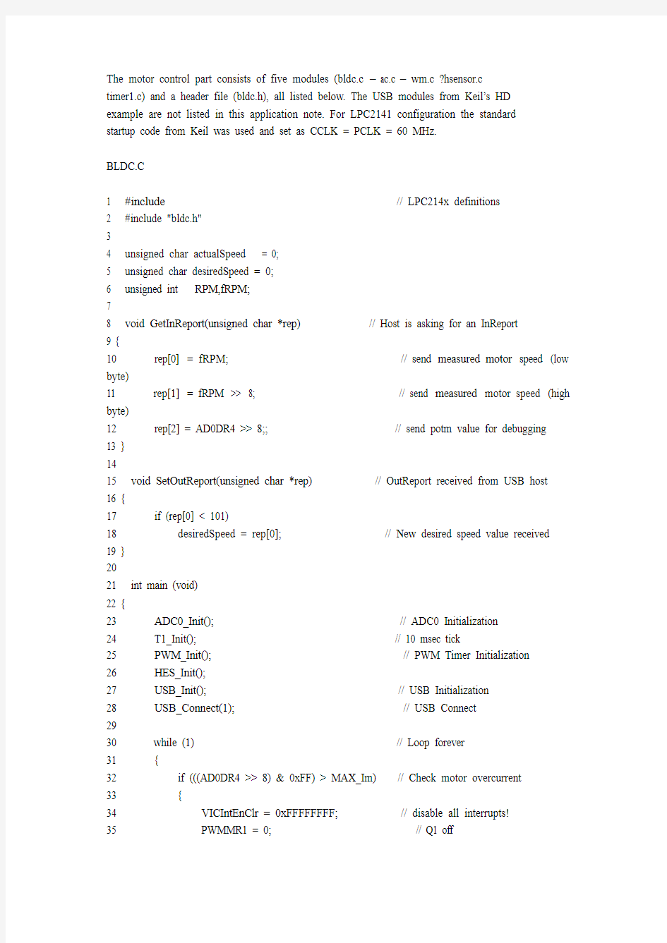

The motor control part consists of five modules (bldc.c – ac.c – wm.c ?hsensor.c
timer1.c) and a header file (bldc.h), all listed below. The USB modules from Keil’s HD
example are not listed in this application note. For LPC2141 configuration the standard
startup code from Keil was used and set as CCLK = PCLK = 60 MHz.
BLDC.C
1 #include
2 #include "bldc.h"
3
4 unsigned char actualSpeed = 0;
5 unsigned char desiredSpeed = 0;
6 unsigned int RPM,fRPM;
7
8 void GetInReport(unsigned char *rep) // Host is asking for an InReport
9 {
10 rep[0] = fRPM; // send measured motor speed (low byte)
11 rep[1] = fRPM >> 8; // send measured motor speed (high byte)
12 rep[2] = AD0DR4 >> 8;; // send potm value for debugging
13 }
14
15 void SetOutReport(unsigned char *rep) // OutReport received from USB host
16 {
17 if (rep[0] < 101)
18 desiredSpeed = rep[0]; // New desired speed value received
19 }
20
21 int main (void)
22 {
23 ADC0_Init(); // ADC0 Initialization
24 T1_Init(); // 10 msec tick
25 PWM_Init(); // PWM Timer Initialization
26 HES_Init();
27 USB_Init(); // USB Initialization
28 USB_Connect(1); // USB Connect
29
30 while (1) // Loop forever
31 {
32 if (((AD0DR4 >> 8) & 0xFF) > MAX_Im) // Check motor overcurrent
33 {
34 VICIntEnClr = 0xFFFFFFFF; // disable all interrupts!
35 PWMMR1 = 0; // Q1 off
36 PWMMR2 = 0; // Q2 off
37 PWMMR3 = 0; // Q3 off
38 PWMMR4 = 0; // Q4 off
39 PWMMR5 = 0; // Q5 off
40 PWMMR6 = 0; // Q6 off
41 PWMLER = 0x7F; // enable PWM0-PWM6 match latch (reload)
42 while (1) ; // wait for a RESET
43 }
44
45 if (f_10ms) // every 10 mseconds
46 {
47 f_10ms = 0;
48
49 if (actualSpeed > desiredSpeed)
50 actualSpeed --;
51 else if (actualSpeed < desiredSpeed)
52 actualSpeed ++;
53
54 RPM = 10000000 / T0CR0; // calculate motor speed
55 fRPM = ((fRPM * 15) + RPM) / 16; // filter it
56 }
57 }
58 }
7.2 ADC.C
1 #include
2
3 void ADC0_Init(void)
4 {
5 PINSEL1 |= 0x00040000; // P0.25 = AIN0.4
6 AD0CR = 0x00200F10; // initialise ADC0, select AIN4
7 AD0CR |= 0x00010000; // start burst mode now, see errata ADC.2
7.3 PWM.C
1 #include
2
3 void PWM_Init(void)
4 {
5 PINSEL0 |= 0x000A800A; // select PWM1-4 and PWM6
6 PINSEL1 |= 0x00000400; // select PWM5
7
8 PWMPR = 20; // prescaler to 20, timer runs at 60 MHz / 20 = 3 MHz
9 PWMPC = 0; // prescale counter to 0
10 PWMTC = 0; // reset timer to 0
11 PWMMR0 = 100; // -> PMW base frequency = 3 MHz / 100 = 30 KHz
12 PWMMR1 = 0; // Match 1 for Q1 (off)
13 PWMMR2 = 0; // Match 2 for Q2 (off)
14 PWMMR3 = 0; // Match 3 for Q3 (off)
15 PWMMR4 = 0; // Match 4 for Q4 (off)
16 PWMMR5 = 0; // Match 5 for Q5 (off)
17 PWMMR6 = 0; // Match 6 for Q6 (off)
18 PWMMCR = 0x00000002; // reset TC on MR0
19 PWMPCR = 0x7E00; // enable PWM1 - PWM6 outputs
20 PWMLER = 0x7F; // enable PWM0 - PWM6 match latch (reload)
21 PWMTCR = 0x09; // enable PWM mode and start timer
22 }