RO3103E;中文规格书,Datasheet资料
?Ideal for 418.00MHz Transmitters ?Very Low Series Resistance ?Quartz Stability
?Surface-Mount, Ceramic Case with 21mm 2 Footprint ?
Complies with Directive 2002/95/EC (RoHS)
The RO3103E is a true one-port, surface-acoustic-wave (SAW) resonator in a surface-mount, ceramic case. It provides reliable, fundamental-mode, quartz frequency stabilization of fixed-frequency transmitters 418.00 MHz
SAW Resonator
RO3103E
1.
Frequency aging is the change in f C with time and is specified at +65°C or less. Aging may exceed the specification for prolonged temperatures
above +65°C. Typically, aging is greatest the first year after manufacture, decreasing in subsequent years.
2.
The center frequency, f C , is measured at the minimum insertion loss point, IL MIN , with the resonator in the 50? test system (VSWR ≤ 1.2:1). The shunt inductance, L TEST , is tuned for parallel resonance with C O at f C . Typically, f OSCILLATOR or f TRANSMITTER is approximately equal to the resonator f C .
3.One or more of the following United States patents apply: 4,454,488 and 4,616,197.
4.Typically, equipment utilizing this device requires emissions testing and government approval, which is the responsibility of the equipment manufacturer.
5.Unless noted otherwise, case temperature T C =+25°C±2°C.
6.
The design, manufacturing process, and specifications of this device are
subject to change.
7.Derived mathematically from one or more of the following directly measured parameters: f C , IL, 3dB bandwidth, f C versus T C , and C O .8.
Turnover temperature, T O , is the temperature of maximum (or turnover) frequency, f O . The nominal frequency at any case temperature, T C , may be calculated from: f =f O [1-FTC (T O -T C )2]. Typically oscillator T O is approximately equal to the specified resonator T O .
9.
This equivalent RLC model approximates resonator performance near the resonant frequency and is provided for reference only. The capacitance C O is the static (nonmotional) capacitance between the two terminals measured at low frequency (10MHz) with a capacitance meter. The
measurement includes parasitic capacitance with "NC” pads unconnected. Case parasitic capacitance is approximately 0.05pF. Transducer parallel capacitance can by calculated as: C P ≈C O -0.05pF.10.
Tape and Reel Standard Per ANSI / EIA 481.
CAUTION: Electrostatic Sensitive Device. Observe precautions for handling.Notes:
Pb
Equivalent LC Model
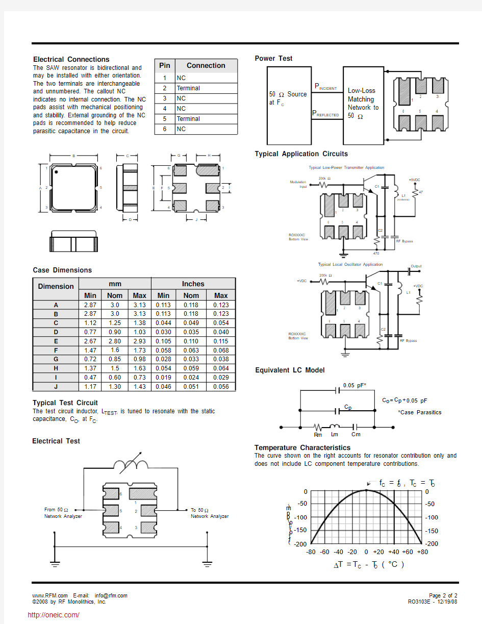
Temperature Characteristics
The curve shown on the right accounts for resonator contribution only and does not include LC component temperature contributions.
Pin
Connection
1NC
2Terminal 3NC 4NC 5Terminal 6
NC
Power Test
Electrical Connections
The SAW resonator is bidirectional and may be installed with either orientation. The two terminals are interchangeable and unnumbered. The callout NC
indicates no internal connection. The NC pads assist with mechanical positioning and stability. External grounding of the NC pads is recommended to help reduce parasitic capacitance in the circuit.
Typical Test Circuit
The test circuit inductor, L TEST , is tuned to resonate with the static capacitance, C O , at F C .
Electrical Test
Typical Application Circuits
Case Dimensions Dimension
mm Inches
Min
Nom
Max
Min
Nom
Max
A 2.87 3.0 3.130.1130.1180.123
B 2.87 3.0 3.130.1130.1180.123
C 1.12 1.25 1.380.0440.0490.054
D 0.770.90 1.030.0300.0350.040
E 2.67 2.80 2.930.1050.1100.115
F 1.47 1.6 1.730.0580.0630.068
G 0.720.850.980.0280.0330.038
H 1.37 1.5 1.630.0540.0590.064
I 0.470.600.730.0190.0240.029J
1.17
1.30
1.43
0.046
0.051
0.056
分销商库存信息: RFM
RO3103E
相关文档
最新文档
- 公司动员大会心得体会
- 实习生动员大会总结7篇
- 元旦演讲稿500字6篇
- 德育活动指导思想
- 2023年关于学校团委工作计划3篇
- 辞旧迎新庆元旦的演讲稿(精选11篇)
- 2021南京育英外国语学校小升初招生入学攻略
- 2023庆元旦主题演讲稿2篇_1
- 小学学校校长述职报告3篇
- 2023庆祝元旦演讲稿(最新10篇)
- 大学引导团员青年培育和践行社会主义核心价值观措施
- 青奥进校园青奥进课堂
- 南京市体育局、南京市教育局关于印发进一步深化体教融合全面促进青少年健康发展的指导意见的通知
- 同站台换乘实现地铁跨线运行线路设计技术研究
- 城市轨道交通换乘方式的选择与分析
- 城市轨道交通换乘站客流组织特点及措施
- 地铁平行换乘站的换乘方式探究
- 轨道交通换乘站
- [广州地铁,站台,平行,其他论文文档]广州地铁沙园站同站台平行换乘方式的设计体会
- 城市轨道交通换乘分析及改善措施