3590S-2-502L;3590S-2-102L;3590S-2-103L;3590S-2-203L;3590S-1-502L;中文规格书,Datasheet资料

Speci? cations are subject to change without notice.
Customers should verify actual device performance in their speci? c applications.
*RoHS Directive 2002/95/EC Jan. 27, 2003 including annex and RoHS Recast 2011/65/EU June 8, 2011.
Stop Strength..............................................................................................................................................................................45 N-cm (64 oz.-in.) minimum Mechanical Angle ...........................................................................................................................................................................................3600 ° +10 °, -0 °Torque (Starting & Running) ................................................................................................................................0.35 N-cm (0.5 oz.-in.) maximum (unsealed) 1.1 N-cm (1.5 oz.-in.) maximum (sealed) Mounting ..............................................................................................................................................................................55-80 N-cm (5-7 lb.-in.) (plastic) 90-113 N-cm (8-10 in.-lb.) (metal)Shaft Runout......................................................................................................................................................................................0.13 mm (0.005 in.) https://www.sodocs.net/doc/3215681966.html,teral Runout ...................................................................................................................................................................................0.20 mm (0.008 in.) T.I.R.Shaft End Play ...................................................................................................................................................................................0.25 mm (0.010 in.) T.I.R.Shaft Radial Play ...............................................................................................................................................................................0.13 mm (0.005 in.) T.I.R.Pilot Diameter Runout .......................................................................................................................................................................0.08 mm (0.003 in.) T.I.R.Backlash ............................................................................................................................................................................................................1.0 ° maximum Weight ........................................................................................................................................................................................................Approximately 19 G Terminals ................................................................................................................................................................................................Solder lugs or PC pins Soldering Condition
Manual Soldering...........................................................96.5Sn/3.0Ag/0.5Cu solid wire or no-clean rosin cored wire; 370 °C (700 °F) max. for 3 seconds Wave Soldering ...................................................................................96.5Sn/3.0Ag/0.5Cu solder with no-clean ? ux; 260 °C (500 °F) max. for 5 seconds Wash processes .......................................................................................................................................................................................Not recommended Marking .....................................Manufacturer’s name and part number, resistance value and tolerance, linearity tolerance, wiring diagram, and date code.Ganging (Multiple Section Potentiometers) ......................................................................................................................................................1 cup maximum Hardware ............................................................................................................One lockwasher and one mounting nut is shipped with each potentiometer.NOTE: For Anti-rotation pin add 91 after con? guration dash number. Example: -2 becomes -291 to add AR pin.1At room ambient: +25 °C nominal and 50 % relative humidity nominal, except as noted. 2Consult manufacturer for complete speci? cation details for resistances below 1k ohms.
BOLDFACE LISTINGS ARE IN STOCK AND READILY AVAILABLE
THROUGH DISTRIBUTION. FOR OTHER OPTIONS CONSULT FACTORY.ROHS IDENTIFIER: L = COMPLIANT
Recommended Part Numbers
(Printed Circuit)
(Solder Lug)(Solder Lug)Resistance (Ω)
Resolution (%)
3590P-2-102L 3590S-2-102L 3590S-1-102L 1,000.0293590P-2-202L 3590S-2-202L 3590S-1-202L 2,000.0233590P-2-502L 3590S-2-502L 3590S-1-502L 5,000.0253590P-2-103L 3590S-2-103L 3590S-1-103L 10,000.0203590P-2-203L 3590S-2-203L 3590S-1-203L 20,000.0193590P-2-503L 3590S-2-503L 3590S-1-503L 50,000.0133590P-2-104L
3590S-2-104L
3590S-1-104L
100,000
.009
*R
o H S C O M
P L I A N T
https://www.sodocs.net/doc/3215681966.html,/
3590 - Precision Potentiometer
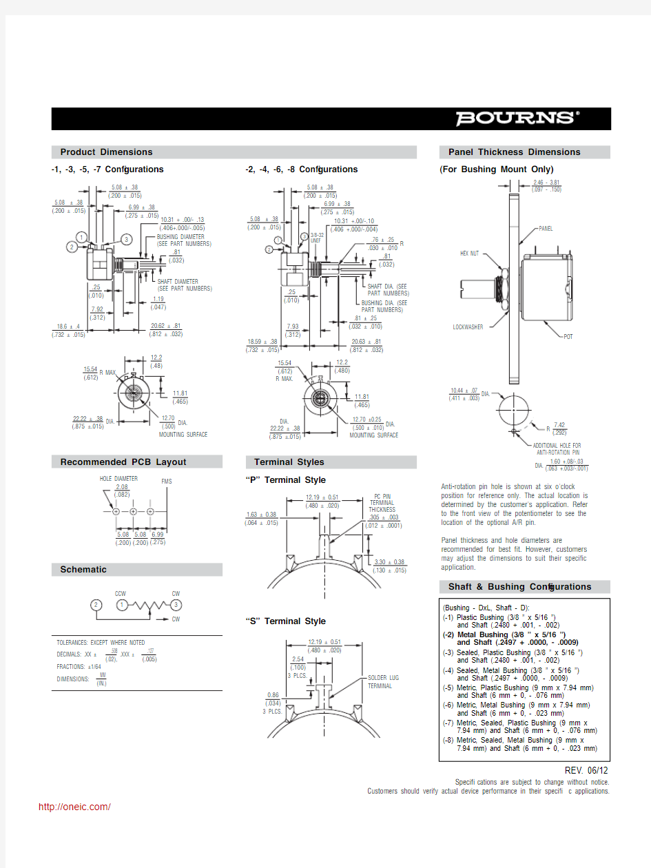
Panel Thickness Dimensions
(For Bushing Mount Only)
1.60 +.08/-.03
(.063 +.003/-.001)
DIA.
ANTI-ROTATION PIN
Anti-rotation pin hole is shown at six o'clock
position for reference only. The actual location is
determined by the customer's application. Refer
to the front view of the potentiometer to see the
location of the optional A/R pin.
Panel thickness and hole diameters are
recommended for best fit. However, customers
may adjust the dimensions to suit their specific
application.
Product Dimensions
Speci? cations are subject to change without notice.
Customers should verify actual device performance in their speci? c applications.
REV. 06/12 MOUNTING SURFACE
-2, -4, -6, -8 Con? gurations
-1, -3, -5, -7 Con? gurations
Recommended PCB Layout
HOLE DIAMETER
5.08
(.200)
5.08
(.200)
6.99
(.275)
Schematic
TOLERANCES: EXCEPT WHERE NOTED
.508 .127
DECIMALS: .XX ±
(.02),
.XXX ±
(.005)
FRACTIONS: ±1/64
MM
DIMENSIONS:
(IN.)
Shaft & Bushing Con? gurations
(Bushing - DxL, Shaft - D):
(-1) Plastic Bushing (3/8 ” x 5/16 ”)
and Shaft (.2480 + .001, - .002)
(-2) Metal Bushing (3/8 ” x 5/16 ”)
and Shaft (.2497 + .0000, - .0009)
(-3) Sealed, Plastic Bushing (3/8 ” x 5/16 ”)
and Shaft (.2480 + .001, - .002)
(-4) Sealed, Metal Bushing (3/8 ” x 5/16 ”)
and Shaft (.2497 + .0000, - .0009)
(-5) Metric, Plastic Bushing (9 mm x 7.94 mm)
and Shaft (6 mm + 0, - .076 mm)
(-6) Metric, Metal Bushing (9 mm x 7.94 mm)
and Shaft (6 mm + 0, - .023 mm)
(-7) Metric, Sealed, Plastic Bushing (9 mm x
7.94 mm) and Shaft (6 mm + 0, - .076 mm)
(-8) Metric, Sealed, Metal Bushing (9 mm x
7.94 mm) and Shaft (6 mm + 0, - .023 mm)
Terminal Styles
“P” Terminal Style
“S” Terminal Style
https://www.sodocs.net/doc/3215681966.html,/
分销商库存信息:
BOURNS
3590S-2-502L3590S-2-102L3590S-2-103L 3590S-2-203L3590S-1-502L3590S-2-104L 3590S-1-203L3590S-2-501L3590S-2-202L 3590S-1-503L3590S-2-503L3590S-1-104L 3590S-291-102L3590S-291-203L3590S-291-502L 3590S-1-201L3590S-1-501L3590S-2-101L 3590S-2-201L3590P-1-102L3590P-1-103L 3590P-1-201L3590P-1-502L3590S-1-102L 3590S-1-103L3590S-2-252L3590P-291-501L 3590P-2-102L3590P-2-201L3590P-2-203L 3590P-2-502L3590S-1-202L3590S-6-102L 3590S-6-201L3590S-6-202L3590S-6-203L 3590S-6-501L3590P-1-104L3590S-6-502L 3590S-4-102L3590S-4-103L3590S-4-202L 3590S-4-203L3590S-4-502L3590S-8-102L 3590S-8-103L3590S-8-202L3590P-2-104L 3590P-4-103L3590P-4-202L3590S-6-503L 3590S-6-104L3590S-4-104L3590P-4-503L 3590P-4-104L3590S-2-5023590S-1-102 3590S-1-1033590S-1-1043590S-1-203 3590S-1-5023590S-1-5033590S-2-102 3590S-2-1033590S-2-1043590S-2-203 3590S-2-5033590S-1-2023590S-2-202 3590S-2-501