建环资料外文
ICR07-A1-156
PARAMETRIC STUDIES OF THERMOACOUSTIC REFREIGERATORS
DRIVEN BY SOLAR ENERGY
Guozhong DING, Xiaoqing ZHANG, Fangzhong GUO, Suyi HUANG
School of Energy and Power Engineering,Huazhong University of Science and
Technology,Wuhan,Hubei,430074,P.R.China
Fax:86-27-87540724 email:ding_guo_zhong@https://www.sodocs.net/doc/632521905.html,
ABSTRACT
The article discusses the technical feasibility of thermoacoustic refrigerator driven by solar energy. A concept of a thermoacoustic stack (TARS)is proposed and the thermoacoutic Stirling scheme is adopted as a basic system for parametric study of a refrigeration energy transducer driven by solor energy. The relationships between pressures of input pressure, resonator pressure and output pressure and between working frequency and buffer volume are discussed, and a series of problems have been investigated by computation modeling . The main problems are the limitation of specific cold capacity in unit volume, the preferred resonance frequency and the required thermal properties of working medium in TA system. Based on the presented study an experimental prototype of the proposed system is being established.
INTRODUCTION
Over the last three decades, with the fast development of the thermoacoustic technology, thermoacousic engines(refrigerators and prime movers) reached a great benefit in terms of simplicity, reliability and cost. Moreover, the employment of nonpollution working fluids makes thermoacoustic devices being very attracitive from an environmental point of view. A comprehensive review of the principles of thermoacoustic heat transport can be found in the tutorial article of Swift[1,2].Usually solar energy power density is about 800W/m 2。For a 20m 2 air-conditioning room, 3000W refrigeration capacity supply is required. Suppose the temperatures of two heat source of a refrigerator is 400K and 300K and the effective absorb coefficient is 0.5, 400W/m 2 power can be absorbed, then Carnot efficiency is 25.0=η, the required solar energy area is 30m 2 under the condition of Carnot efficiency. The best efficiency of thermoacoustic engines is 0.4 of Carnot efficiency reported by G . Swift reported[3]. It is obvious that the refrigeration capacity is insufficient if supplied only by solar energy. Whether is there a technical feasibility of thermoacoustic refrigerator driven by solar energy? In order to solve the problem, the power density for application has to be estimated. According to current thermoacoutic refrigerator ’s levels and there are being some problems, such as power density, critical temperature and feasibility, effectiveness. A original scheme of thermoacoustic refrigerators stacks(TARS) can be exploited, it can be assembled by a lot of TARS chips according to the requirement of target objects.
The most significant problem with prior thermoacoustic engines and refrigerators is that they have a very low power density. They are typically much larger and more massive for the amount of output work they produce, than other types of engines and refrigerators. A compound engine by coupling Ceperley ’s
torus-shaped traveling-wave engine with a cylindrical standing-wave resonator, made by Greg Swift[3], in an effort to produce greater output power from the traveling-wave component, without damping the standing-wave oscillator. But the engine develops low energy density because the design still relies mainly on geometry to produce an engine that is acoustically resonant.H. Sugita et al. [4] reported an experimental study on thermally actuated pressure wave generator for space cryocooler, the maximum work amplification ratio of 1.6 was obtained in the work amplifier with solid displacers. It is the best level in thermoacoustic refrigetators so far. The paper will adopt Sugita model and the analysis of the influence of buffer volume on working frequency will be also discussed. According to the prototype, the power density of thermoacoutic refrigerator that is estimatly compared with that of target objects to decide the numbers of TARS chips. Another key problem of thermoacoustic refrigeration driven by solar energy is that the influence of temperature difference of heat sources on the performance of thermoacoustic refrigeration, which decides the technical feasibility of thermoacustic refrigerator. This will be also discussed in the paper.
1. SCHEME STUDY OF THE TECHNICAL FEASIBILITY OF THERMOACOUSTIC
REFRIGERATOR DRIVEN BY SOLAR ENERGY
The paper proposes a conceptual scheme that the key component is a thermoacoustic stacks(TARS) with resonator and buffer volume. Its optimistic target is unit volume refrigeration capacity, which decides the number of TARS in one square meter. In terms of required refrigeration, the number of TARS calculated can be compared with the maximum number TARS that can be laid in one square meter. According to the compared results, the scheme of thermoacoustic refrigerator driven by solar energy whether is with reason can be verdicted.
Power output of the TARS depends on the physical dimensions of the pistons and heat exchangers in the device, the static pressure of the working fluid and the thermal gradient across the device. The frequency of operation is determined by the engineering properties of all the heat exchangers, and to a less extent, by the geometry of the acoustic cavity. When affixed to a blackened metal absorber panel, or other radiant-energy absorbing material, and to a cooling means on its opposite face, the TAR can convert heat from radiant energy, such as sunlight, into electrical energy. In this respect, the TAR responds to a wider bandwidth of radiant energy than photovoltaic cells. It can absorb and use wavelengths that are below the photovoltaic threshold for most materials.Energy conversion efficiencies are directly related to the temperature gradient across the TAR. According to above said description, key parameters of thermoacoustic refrigerator driven by solar energy, which decided by optimistic target of unit volume refrigeration capacity, are the relationship between input pressures, resonator pressure and output pressure, and the relationship between working frequency and buffer volume,and the location of stack and wire mesh have an important effect on performance of TARS.
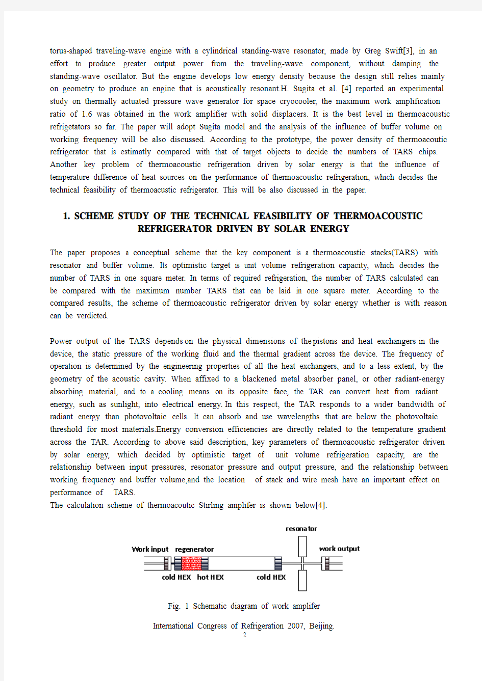
The calculation scheme of thermoacoutic Stirling amplifer is shown below[4]:
Fig. 1 Schematic diagram of work amplifer
1.1 Basic equation of thermoacoustic systems
The network scheme figure of resonator of Stirling engine is shown below[5]:
Fig.2 the network scheme of variation volume resonator for Stirling engine
s R is the sum of dissipation of the engine system, s p m m + is the total mass of vibration, s k is strain coefficient of spring systems, TA R is the actual load of the Stirling engine system.
It is obvious that the characteristic frequency of the system is as follows: s s m k f π21
0=
(1) where dr m ech gas s k k k k ++=, dr p s m m m m ++=0s .
This is a optimation frequency of the system for the design of thermoacousitc Stirling engine.In fact, the length ,geometry and diameter of resonator and void volume have an important effect on the resonance frequency.
The network model of resonator is expressed as follows[6]:
??
????''??????-=??????''in in end end J p a V i J p 1/012ρω (2) The network transport equation of thermoacoustic components is expressed as follows[6]:
???????????
???????+++-+-++++=??????----in in x x
x x x x x x J p e e e e z e e z e e J p 21212121212211212121211212)()(1)(γγγγγγγγγγγγγγγγγγγγγγγγγγ (3) yz 4212121++-=ααγ, yz 4212122++=ααγ
The equation is suitable for all kinds of stacks such as parallel plates, circular pores, meshes, and pin-array . the work flux is then given by[7,8]
t r u p x I ?????=11)( (4)
The symbol t >? written as follows: ?c o s ||||5.0)(11q p x W = (5) For modeling the output work and pressure variation of TARS, momentum equation and pressure equations respect to thermoacoustic components need to be established according to Fig. 1[11]. 1.2 Influence of buffer volume on working frequency As shown in Fig.1, the equations of continuity and mass conservation lead to 04030201P P P P === 004030201=+++Q Q Q Q where P is gas pressure and Q is volume flow rate. In terms of the fluid network principle, for a pipe with length L and flow area A, when the gas viscosity is ignored, the relation between the input impedance and output impedance of the system, is given[9] L C L L C Z a L Z Z i a L Z Z i Z ωωt a n 1t a n 10++= (6) where a is acoustic speed, C Z is characteristic impedance which is equal to A a /ρ to an idealized pipe, ρ is fluid density, ω is angular frequency, 0Z is input impedance, L Z is output impedance. In terms of the definition of impedance, we get: 0111104 030201=+++Z Z Z Z (7) Using Eq.(6), the frequency equation can be expressed as 011t a n 1t a n 1t a n 1t a n 10403222222 2221111111=+++++++Z Z a V i a L Z Z i a L Z Z i a V i a L Z Z i a L Z Z i L C C L L C C L ρωωωρωωω (8) 1.3 Influence of temperature difference on performance of TARS The thermoacoustic refrigerator driven by solar energy has a low temperature difference between the hot end and the cold ends of the regenerator (stack), a gamma-configuration engine requireds a normal 90 degree phase angle between the displacer and the power piston. Some characteristics of the low temperature difference Stirling refrigerator are as follows:(1)Displacer to power piston swept volume ratio is large;(2)Diameter of displacer cylinder and displacer is large;(3)Displacer is short;(4)Displacer stroke is small;(5)Working frequency is low.The characteristics are the same with external actuacted thermoacoustic Stirling engine. 1.4 Influence of kinds and location of stacks(regenerator) on performance of TARS Work gain has a peak with the length of stacks under the condition of different wire mesh. The influence of stack can be calculated by DeltaE and the result show that an optimistic length of stacks(regenerator) must be choosed. 2 THE CALCULATION RESULT AND DISCUSSION OF A PROTOTYPE SCHEME 2.1 The input work and loss of TARS Fig. 3 Input work at an actuator PV work is shown in Fig.3 under the condition of different working frequency。This is the input work at the compressor piston. It tells us that a larger input work under the condition of the same amplification ratio is more benificial. Fig.4 is the dissipated work at the displacer. The narrow PV shape indicates the high quality factor of the resonator to generate the standing wave. Fig. 4 Lost work at buffer volumes 2.2 The relationship between pressures of TARS Fig.5 Pressure variation with time The pressure variation is shown in Fig.5. It is obvious that there are a phase angle difference between the compression piston and displacer and buffer volume. It tells us that the three components need optimistic design to produce resonant working frequency under the condition of three inherent charcteristic frequency. From Fig.5, a difference of the amplification between pressures can be found. It tells us that a larger input pressure can reach a larger output work at the condition of the same pressure ratio. 2.3 influence of buffer volume on working frequency The computed result of the dependence of specific buffer volume on resonance frequency with helium as the working fluid is shown in Fig.6. The resonance frequency of the resonator can be decreased by means of increasing the buffer volume in each arrangement[10]. The arrangement of Fig.1 is the best for the frequency reduction. Fig. 6 Relationship between resonance frequency and buffer volume From Fig.6 we can find that an optimical buffer volume is coincided with the design resonance frequency. 2.4 Influence of kinds and location of stacks on performance of TARS Fig.7 Influence of the length of stacks and wire mesh on performance of TARS From Fig.7 the length of stack and wire mesh must be an optimistic choice. CONCLUSION In this paper, we proposed a prototype scheme of a thermoacoustic refrigerator driven by solar energy. The relationships between input pressure, resonator pressure and output pressure and between working frequency and buffer volume indicate the conditions of technical feasibility of a thermoacoustic refrigerator. By discussing the parameters, a Stirling scheme of thermoacoustic refrigerator driven by solar energy must adopte work amplifier and buffer volume, and correspongding to a certain resonance frequency, there is an optimical buffer volume and a stack(regenerator). By stacking the modules of the thermoacoustic stacks, a required refrigeration capacity can be capable of satisfaction. ACKNOWLEDGEMENT The projects is sponsored by natural science foundation of China(50676068). REFERENCES 1. G.W.Swift, 1988,Thermoacoustic engines,J.Acoust. Soc.Amer.84(8): 1145-1180. 2. S.Backhaus and G.W. Swift, 2000,A thermoacoustic-Stirling heat engine:Detailed study, J.Acoust. Soc.Amer.107(6):3148-3166. 3. S. Backhaus and,G..W. Swift, 1999,A thermoacoustic Stirling heat engine, Nature 399:335-338. 4. H. Sugita et al., 2004,Experimental study on thermally actuated pressure wave generator for space cryocooler, Cryogenics 44:431-437. 5. Qiu Tu et al., 2003, Influence of temperature gradient on acoustic characteristic parameters of stack in TAE , Int. J. Engineering Science 41(12):1337-1349. 6. Q. Tu et al., 2003,Network model approach for calculating oscillating frequency of thermoacoustic prime mover, Cryogenics 43(6):351-357. 7. Arnott WP, Bass HE, Raspet R. 1991,General formulation of thermoacoustics for stacks having arbitrarily shaped pore cross sections, J.Acoust. Soc.Amer. 90(6):3228-37 8. A.Tominaga, 1995,Thermodynamic aspects of thermoacoustic theory, Cryogenics 35(7):427-440. 9. J.M. Kirshner, S. Katz, 1975,Design theory of fluidic components. New York:Academic Press. 10. G.B. Chen et al., 2002,Influence of buffer on resonance frequency of thermoacoustic engine, Cryogenics 42:223-227. 11. Y. Matsubara et al., 2003,Pressure wave generator for a pulse tube cooler, Cryocoolers 12:343-348. 微软Visual Studio 1微软Visual Studio Visual Studio 是微软公司推出的开发环境,Visual Studio可以用来创建Windows平台下的Windows应用程序和网络应用程序,也可以用来创建网络服务、智能设备应用程序和Office 插件。Visual Studio是一个来自微软的集成开发环境IDE,它可以用来开发由微软视窗,视窗手机,Windows CE、.NET框架、.NET精简框架和微软的Silverlight支持的控制台和图形用户界面的应用程序以及Windows窗体应用程序,网站,Web应用程序和网络服务中的本地代码连同托管代码。 Visual Studio包含一个由智能感知和代码重构支持的代码编辑器。集成的调试工作既作为一个源代码级调试器又可以作为一台机器级调试器。其他内置工具包括一个窗体设计的GUI应用程序,网页设计师,类设计师,数据库架构设计师。它有几乎各个层面的插件增强功能,包括增加对支持源代码控制系统(如Subversion和Visual SourceSafe)并添加新的工具集设计和可视化编辑器,如特定于域的语言或用于其他方面的软件开发生命周期的工具(例如Team Foundation Server的客户端:团队资源管理器)。 Visual Studio支持不同的编程语言的服务方式的语言,它允许代码编辑器和调试器(在不同程度上)支持几乎所有的编程语言,提供了一个语言特定服务的存在。内置的语言中包括C/C + +中(通过Visual C++),https://www.sodocs.net/doc/632521905.html,(通过Visual https://www.sodocs.net/doc/632521905.html,),C#中(通过Visual C#)和F#(作为Visual Studio 2010),为支持其他语言,如M,Python,和Ruby等,可通过安装单独的语言服务。它也支持的 XML/XSLT,HTML/XHTML ,JavaScript和CSS.为特定用户提供服务的Visual Studio也是存在的:微软Visual Basic,Visual J#、Visual C#和Visual C++。 微软提供了“直通车”的Visual Studio 2010组件的Visual Basic和Visual C#和Visual C + +,和Visual Web Developer版本,不需任何费用。Visual Studio 2010、2008年和2005专业版,以及Visual Studio 2005的特定语言版本(Visual Basic、C++、C#、J#),通过微软的下载DreamSpark计划,对学生免费。 2架构 Visual Studio不支持任何编程语言,解决方案或工具本质。相反,它允许插入各种功能。特定的功能是作为一个VS压缩包的代码。安装时,这个功能可以从服务器得到。IDE提供三项服务:SVsSolution,它提供了能够列举的项目和解决方案; SVsUIShell,它提供了窗口和用户界面功能(包括标签,工具栏和工具窗口)和SVsShell,它处理VS压缩包的注册。此外,IDE还可以负责协调和服务之间实现通信。所有的编辑器,设计器,项目类型和其他工具都是VS压缩包存在。Visual Studio 使用COM访问VSPackage。在Visual Studio SDK中还包括了管理软件包框架(MPF),这是一套管理的允许在写的CLI兼容的语言的任何围绕COM的接口。然而,MPF并不提供所有的Visual Studio COM 功能。 Load and Ultimate Moment of Prestressed Concrete Action Under Overload-Cracking Load It has been shown that a variation in the external load acting on a prestressed beam results in a change in the location of the pressure line for beams in the elastic range.This is a fundamental principle of prestressed construction.In a normal prestressed beam,this shift in the location of the pressure line continues at a relatively uniform rate,as the external load is increased,to the point where cracks develop in the tension fiber.After the cracking load has been exceeded,the rate of movement in the pressure line decreases as additional load is applied,and a significant increase in the stress in the prestressing tendon and the resultant concrete force begins to take place.This change in the action of the internal moment continues until all movement of the pressure line ceases.The moment caused by loads that are applied thereafter is offset entirely by a corresponding and proportional change in the internal forces,just as in reinforced-concrete construction.This fact,that the load in the elastic range and the plastic range is carried by actions that are fundamentally different,is very significant and renders strength computations essential for all designs in order to ensure that adequate safety factors exist.This is true even though the stresses in the elastic range may conform to a recognized elastic design criterion. It should be noted that the load deflection curve is close to a straight line up to the cracking load and that the curve becomes progressively more curved as the load is increased above the cracking load.The curvature of the load-deflection curve for loads over the cracking load is due to the change in the basic internal resisting moment action that counteracts the applied loads,as described above,as well as to plastic strains that begin to take place in the steel and the concrete when stressed to high levels. In some structures it may be essential that the flexural members remain crack free even under significant overloads.This may be due to the structures’being exposed to exceptionally corrosive atmospheres during their useful life.In designing prestressed members to be used in special structures of this type,it may be necessary to compute the load that causes cracking of the tensile flange,in order to ensure that adequate safety against cracking is provided by the design.The computation of the moment that will cause cracking is also necessary to ensure compliance with some design criteria. Many tests have demonstrated that the load-deflection curves of prestressed beams are approximately linear up to and slightly in excess of the load that causes the first cracks in the tensile flange.(The linearity is a function of the rate at which the load is applied.)For this reason,normal elastic-design relationships can be used in computing the cracking load by simply determining the load that results in a net tensile stress in the tensile flange(prestress minus the effects of the applied loads)that is equal to the tensile strength of the concrete.It is customary to assume that the flexural tensile strength of the concrete is equal to the modulus of rupture of the 本实验要使用CMOS4046集成电路研究锁相环(PLL )的工作原理。电路包括两个不同的鉴相器和一个VCO 。另外还有一个齐纳二极管参考电压源用在供电调节中,在解调器输出中有一个缓冲电路。用户必须提供环路滤波器。4046具有高输入阻抗和低输出阻抗,容易选择外围元件。 注意事项 1. 本实验较为复杂,进入实验室之前,确认你已经弄懂了电路预计应该怎样工作。对某样东西还没有充分分析之前,不要去尝试制作它。在开始实验之前要通读本文。 2. 在实验第一部分得到的数据要用来完成实验的其它任务。 所以要仔细对待这部分内容。 3. 小心操作4046芯片,CMOS 集成电路很容易损坏。避免静电释放,使用10k Ω电阻把信号发生器的输出耦合到 PLL 。在关掉4046供电电源之前先关闭信号发生器,或者从信号输入端给整个电路供电。要避免将输出端对电源或对地短路,TTL 门电路可以容忍这种误操作但 CMOS 不能(要注意松散的导线)。CMOS 输出也没有能力驱动电容负载。VSS 应该接地,VDD 应该接5V ,引脚5应该接地(否则VCO 被禁止)。 1 VCO 工作原理 阅读数据手册中的电路描述。 VCO 常数(0K 单位为弧度/秒-伏)是工作频率 变化与输入电压(引脚9上)变化之比值。测量出0K ,即,画出输出频率关于 输入电压的曲线。确认数据范围要覆盖5kHz 到50kHz 。对于R1, R2 和C 的各种参数取值进行测量,确定 0K 对于R1 ,R2 和C 是怎样的近似关系。测量VCO 输出的上升和下降时间,研究电容性负载的影响。2 无源环路滤波器 无源环路滤波器位于鉴相器输出与VCO 输入之间。此滤波器对鉴相器输出中 的高次谐波进行衰减,并控制环路的强度。通常用一个简单 RC 滤波器就可以满足要求,这种设计能避免有源滤波器设计中固有的电平移动和输出限制的恼人问 题。但另外一方面,有源滤波器可以提供更优越的性能。 2.1 相位比较器首先来看一下4046的相位比较器II 的输出。该输出端是一个三态器件,这可以在环路锁定时减小波纹。与存在两倍基频拍频的情况不同,这里没有任何拍频。糟糕的方面是,当我们需要为环路建立一个框图时, D K 却不能很好地定义。当向上或向下驱动之一接通时,输出端表现为电压源。但是当输出端悬浮时,它实质上为一个电流源(一个 0A 电流源)。因此D K 的值将依赖于给定的滤波器。考 察图1。 图1 相位比较器II 的输出 图中当向上驱动器接通时,相位比较器输出为 5PO v V ,当向下驱动器接通时,0PO v V ,当相位比较器处在开路状态时,PO D v v 。我们可以求出输出的平均值: 外文资料翻译 资料来源:《模具设计与制造专业英语》 文章名:Chapter 3 Casting Dies 书刊名:《English for Die & Mould Design and Manufacturing》 作者:刘建雄王家惠廖丕博主编 出版社:北京大学出版社,2002 章节:Chapter 3 Casting Dies 页码:P51~P60 文章译名:铸造模具 Chapter 3 Casting Dies 3.1Casting The first castings were made during the period 4000~3000 B.C., using stone and metal molds for casting copper. Various casting processes have been developed over a long period of time, each with its own characteristics and applications, to meet specific engineering and service requirements. Many parts and components are made by casting, including cameras, carburetors, engine blocks, crankshafts, automotive components, agricultural and railroad equipment, pipes and plumbing fixtures, power tools, gun barrels, frying pans, and very large components for hydraulic turbines. Casting can be done in several ways. The two major ones are sand casting, in which the molds used are disposable after each cycle, and die casting, or permanent molding, in which the same metallic die is used thousands or even millions of times. Both types of molds have three common features. They both have a “plumbing” system to channel molten alloy into the mold cavity. These channels are called sprues, runners, and gates (Fig. 3-1). Molds may be modified by cores which form holes and undercuts or inserts that become an integral part of the casting. Inserts strengthen and reduce friction, and they may be more machinable than the surrounding metal. For example, a steel shaft when properly inserted into a die cavity results in an assembled aluminum step gear after the shot. After pouring or injection, the resulting castings require subsequent operations such trim-ming, inspection, grinding, and repairs to a greater or lesser extent prior to shipping. Premium-quality castings from alloys of aluminum or steel require x-ray soundness that will be acceptable by the customer. Certain special casting processes are precision-investment casting, low-pressure casting, and centrifugal casting. forced concrete structure reinforced with an overviewRein Since the reform and opening up, with the national economy's rapid and sustained development of a reinforced concrete structure built, reinforced with the development of technology has been great. Therefore, to promote the use of advanced technology reinforced connecting to improve project quality and speed up the pace of construction, improve labor productivity, reduce costs, and is of great significance. Reinforced steel bars connecting technologies can be divided into two broad categories linking welding machinery and steel. There are six types of welding steel welding methods, and some apply to the prefabricated plant, and some apply to the construction site, some of both apply. There are three types of machinery commonly used reinforcement linking method primarily applicable to the construction site. Ways has its own characteristics and different application, and in the continuous development and improvement. In actual production, should be based on specific conditions of work, working environment and technical requirements, the choice of suitable methods to achieve the best overall efficiency. 1、steel mechanical link 1.1 radial squeeze link Will be a steel sleeve in two sets to the highly-reinforced Department with superhigh pressure hydraulic equipment (squeeze tongs) along steel sleeve radial squeeze steel casing, in squeezing out tongs squeeze pressure role of a steel sleeve plasticity deformation closely integrated with reinforced through reinforced steel sleeve and Wang Liang's Position will be two solid steel bars linked Characteristic: Connect intensity to be high, performance reliable, can bear high stress draw and pigeonhole the load and tired load repeatedly. A Wavelet Based Approach for Fast Detection of Internal Fault in Power Transformers The power transformer is one of the most expensive elements of power system and its protection is an essential part of the overall system protection strategy. The differential protection provides the best protection for power transformer. Its operation principle is based on this point that the differential current during an internal fault is higher than normal condition. But, a large transient current (inrush current) can cause mal-operation of differential relays. Then, studies for the improvement of the transformer protection have focused on discrimination between internal short circuit faults and inrush currents in transformers. The magnetizing inrush current has a large second order harmonic component in comparison to internal faults. Therefore , some transformer protection systems are designed to halt operating during the inrush current by sensing this large second order harmonic. The second harmonic component in the magnetizing inrush currents tend to be relatively small in modern large power transformers because of improvements in the power transformer core materials. Also , it has been seen that the fault current can contain higher second order harmonics than the inrush current due to nonlinear fault resistance, CT saturation .the distributed capacitance in the transmission line, which transformer is connected to, or due to the use of extra high voltage underground cables. Various methods have been suggested for overcoming this protection system mal-operation. This paper presents a wavelet based method for discrimination among inrush current, internal short circuit ,external short circuit and energizing and it is not affected by CT saturation and it is able to detect internal faults while transformer energization. Unlike Artificial Neural Network and Fuzzy logic based algorithms. This approach is not system dependent. The operating time of the scheme is less than 10ms. The Daubechies mother wavelet is used with a sample rate of 5 kHz. Then , the differential currents of the three phases are decomposed into two details and only the second level will be considered by using db5 mother wavelet. Discrete Wavelet Transform The wavelet transform is a powerful tool to extract information from the non-stationary signals simultaneously in both time and frequency domains. The ability of the wavelet transform to focus on short time intervals for high-frequency components and long intervals for low-frequency components improves the analysis 外文出处: 《Exploiting Software How to Break Code》By Greg Hoglund, Gary McGraw Publisher : Addison Wesley Pub Date : February 17, 2004 ISBN : 0-201-78695-8 译文标题: JDBC接口技术 译文: JDBC是一种可用于执行SQL语句的JavaAPI(ApplicationProgrammingInterface应用程序设计接口)。它由一些Java语言编写的类和界面组成。JDBC为数据库应用开发人员、数据库前台工具开发人员提供了一种标准的应用程序设计接口,使开发人员可以用纯Java语言编写完整的数据库应用程序。 一、ODBC到JDBC的发展历程 说到JDBC,很容易让人联想到另一个十分熟悉的字眼“ODBC”。它们之间有没有联系呢?如果有,那么它们之间又是怎样的关系呢? ODBC是OpenDatabaseConnectivity的英文简写。它是一种用来在相关或不相关的数据库管理系统(DBMS)中存取数据的,用C语言实现的,标准应用程序数据接口。通过ODBCAPI,应用程序可以存取保存在多种不同数据库管理系统(DBMS)中的数据,而不论每个DBMS使用了何种数据存储格式和编程接口。 1.ODBC的结构模型 ODBC的结构包括四个主要部分:应用程序接口、驱动器管理器、数据库驱动器和数据源。应用程序接口:屏蔽不同的ODBC数据库驱动器之间函数调用的差别,为用户提供统一的SQL编程接口。 驱动器管理器:为应用程序装载数据库驱动器。 数据库驱动器:实现ODBC的函数调用,提供对特定数据源的SQL请求。如果需要,数据库驱动器将修改应用程序的请求,使得请求符合相关的DBMS所支持的文法。 数据源:由用户想要存取的数据以及与它相关的操作系统、DBMS和用于访问DBMS的网络平台组成。 虽然ODBC驱动器管理器的主要目的是加载数据库驱动器,以便ODBC函数调用,但是数据库驱动器本身也执行ODBC函数调用,并与数据库相互配合。因此当应用系统发出调用与数据源进行连接时,数据库驱动器能管理通信协议。当建立起与数据源的连接时,数据库驱动器便能处理应用系统向DBMS发出的请求,对分析或发自数据源的设计进行必要的翻译,并将结果返回给应用系统。 2.JDBC的诞生 自从Java语言于1995年5月正式公布以来,Java风靡全球。出现大量的用java语言编写的程序,其中也包括数据库应用程序。由于没有一个Java语言的API,编程人员不得不在Java程序中加入C语言的ODBC函数调用。这就使很多Java的优秀特性无法充分发挥,比如平台无关性、面向对象特性等。随着越来越多的编程人员对Java语言的日益喜爱,越来越多的公司在Java程序开发上投入的精力日益增加,对java语言接口的访问数据库的API 的要求越来越强烈。也由于ODBC的有其不足之处,比如它并不容易使用,没有面向对象的特性等等,SUN公司决定开发一Java语言为接口的数据库应用程序开发接口。在JDK1.x 版本中,JDBC只是一个可选部件,到了JDK1.1公布时,SQL类包(也就是JDBCAPI) 基于Multisim的锁相环解调系统仿真毕业论文 目录 第1章绪论 (1) 1.1 研究背景 (1) 1.2 研究现状 (1) 1.3 研究容介绍 (2) 第2章基本原理 (3) 2.1 Multisim介绍 (3) 2.2 锁相环基本原理 (5) 2.2.1锁相环的基本组成 (5) 2.2.2 锁相环的工作原理 (5) 第3章调制解调电路设计 (8) 3.1 2FSK调制解调电路设计 (8) 3.1.1 2FSK调制电路设计原理 (8) 3.1.2 2FSK调制单元电路的设计 (9) 3.1.3 2FSK解调单元电路的设计 (13) 3.1.4 2FSK解调电路的整体设计 (15) 3.2 2PSK调制解调电路设计 (17) 3.2.1 2PSK调制解调电路设计原理 (17) 3.2.2 2PSK调制与解调电路的设计与仿真 (18) 3.3 2ASK调制解调电路设计 (19) 3.3.1 2ASK调制解调电路设计原理 (19) 3.3.2 2ASK调制与解调电路的设计与仿真 (20) 3.4 解调结果分析 (22) 总结 (24) 参考文献 (25) 附录:(外文翻译) (26) 致谢 (50) 第1章绪论 1.1 研究背景 实现调频波解调的方法有很多,而锁相环鉴频是利用现代锁相环技术来实现鉴频方法,具有工作稳定失真小,信噪比高等优点,所以被广泛用在通信电路系统中。锁相环路是一种反馈电路,锁相环的英文全称是Phase-Locked Loop,简称PLL。其作用是使得电路相位同步。因锁相环可以实现输出信号频率对输入信号频率的自动跟踪,所以锁相环通常用于闭环跟踪电路。锁相环在工作的过程中,当输出信号的频率与输入信号的频率相等时,输出电压与输入电压保持固定的相位差值,即输出电压与输入电压的相位被锁住,它还具有载波跟踪特性。作为一个窄带跟踪滤波器,可提取淹没在噪声中的信号;用高稳定的参考振荡器锁定,可提供高稳定的频率源;可进行高精度的香味与频率测量等等。如今锁相环解调器在通信、雷达、测量和自动化控制等领域应用极为广泛,随着电子技术的发展,对锁相环解调的研究和应用得到了越来越多的关注。 现在通过分析与研究,加深对锁相环解调方式的理解,并根据它的原理,设计出2FSK、2PSK、2ASK的调制电路,并通过锁相环解调出来。 1.2 研究现状 锁相环解调技术的发展十分迅速,如今已经在很多领域都应用了锁相环解调的理论。可用于手机中、SDH网络中、在汽车MP3无线发射器中‘测量汽车转速都是十分典型的应用。调频波的特点是频率随调制信号幅度的变化而变化,压控振荡器的振荡频率取决于输入电压的幅度。当载波信号的频率与锁相环的固有振荡频率ω0相等时,压控振荡器输出信号的频率将保持ω0不变。若压控振荡器的输入信号除了有锁相环低通滤波器输出的信号uc外,还有调制信号ui,则压控振荡器输出信号的频率就是以ω0为中心,随调制信号幅度的变化而变化的调频波信号。当然,锁相环的许多优越性使得锁相环解调技术在很多我们周围都可以见到的物品中发挥着其巨大的功效。 如今,锁相环路理论与研究日臻完善,应用围遍及整个电子技术领域。随着通信及电子系统的飞速发展,促使集成锁相环和数字锁相环突飞猛进。现在品种齐全繁多,提高系统的工作稳定性和可靠性和小型化,目前仍朝着集成化,数字化,多用化方向迅速发展。 Injection Molding The basic concept of injection molding revolves around the ability of a thermoplastic material to be softened by heat and to harden when cooled .In most operations ,granular material (the plastic resin) is fed into one end of the cylinder (usually through a feeding device known as a hopper ),heated, and softened(plasticized or plasticized),forced out the other end of the cylinder, while it is still in the form of a melt, through a nozzle into a relatively cool mold held closed under pressure.Here,the melt cools and hardens until fully set-up. The mold is then opened, the piece ejected, and the sequence repeated. Thus, the significant elements of an injection molding machine become: 1) the way in which the melt is plasticized (softened) and forced into the mold (called the injection unit); 2) the system for opening the mold and closing it under pressure (called the clamping unit);3) the type of mold used;4) the machine controls. The part of an injection-molding machine, which converts a plastic material from a sold phase to homogeneous seni-liguid phase by raising its temperature .This unit maintains the material at a present temperature and force it through the injection unit nozzle into a mold .The plunger is a combination of the injection and plasticizing device in which a heating chamber is mounted between the plunger and mold. This chamber heats the plastic material by conduction .The plunger, on each stroke; pushes unbelted plastic material into the chamber, which in turn forces plastic melt at the front of the chamber out through the nozzle The part of an injection molding machine in which the mold is mounted, and which provides the motion and force to open and close the mold and to hold the mold close with force during injection .This unit can also provide other features necessary for the effective functioning of the molding operation .Moving 外文文献: Risk Analysis of the International Construction Project By: Paul Stanford Kupakuwana Cost Engineering Vol. 51/No. 9 September 2009 ABSTRACT This analysis used a case study methodology to analyse the issues surrounding the partial collapse of the roof of a building housing the headquarters of the Standards Association of Zimbabwe (SAZ). In particular, it examined the prior roles played by the team of construction professionals. The analysis revealed that the SAZ’s traditional construction project was generally characterized by high risk. There was a clear indication of the failure of a contractor and architects in preventing and/or mitigating potential construction problems as alleged by the plaintiff. It was reasonable to conclude that between them the defects should have been detected earlier and rectified in good time before the partial roof failure. It appeared justified for the plaintiff to have brought a negligence claim against both the contractor and the architects. The risk analysis facilitated, through its multi-dimensional approach to a critical examination of a construction problem, the identification of an effective risk management strategy for future construction projects. It further served to emphasize the point that clients are becoming more demanding, more discerning, and less willing to accept risk without recompense. Clients do not want surprise, and are more likely to engage in litigation when things go wrong. KEY WORDS:Arbitration, claims, construction, contracts, litigation, project and risk The structural design of the reinforced concrete elements was done by consulting engineers Knight Piesold (KP). Quantity surveying services were provided by Hawkins, Leshnick & Bath (HLB). The contract was awarded to Central African Building Corporation (CABCO) who was also responsible for the provision of a specialist roof structure using patented “gang nail” roof计算机专业外文文献及翻译
外文翻译
cmos4046集成电路研究锁相环(pll)的工作原理毕业外文翻译
铸造模具外文文献翻译、中英文翻译
建筑类外文文献及中文翻译
外文资料及其翻译
毕业设计外文翻译资料
基于Multisim的锁相环解调系统仿真毕业论文
模具毕业设计外文翻译(英文+译文)
建筑-外文翻译