QS9321 BLE Module User Manual - v1.2

QS9321 Bluetooth 4.0 Low Energy Module
User Manual
Version 1.2
VERSION HISTORY
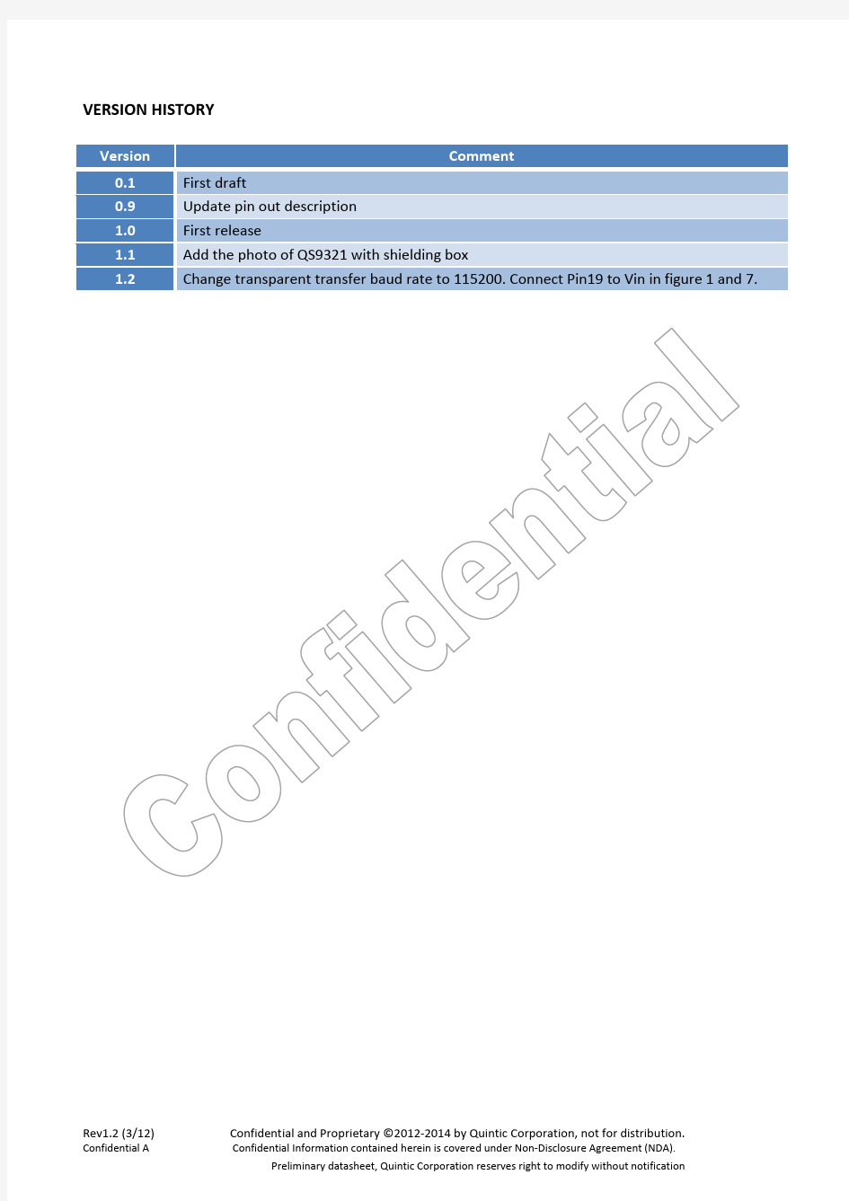
Version Comment
0.1 First draft
0.9 Update pin out description
1.0 First release
1.1 Add the photo of QS9321 with shielding box
1.2 Change transparent transfer baud rate to 115200. Connect Pin19 to Vin in figure 1 and 7.
Table of Contents
1Key Features (1)
2Description (3)
3Pin out (4)
4Electrical Characteristics (6)
5Application Reference Circuit Schematic (7)
6Layout and Physical Dimensions (8)
6.1 Physical dimensions (8)
6.2
711 7.2
1Key Features
◆Bluetooth? 4.0 Low Energy wireless module
●Frequency bands: 2400MHz to 2483.5MHhz
●1Mbps on air data rate
●Slave and Master mode operation
●Support up to 8 simultaneous links in master mode
●128-bit AES coprocessor
●Complete BLE protocol stack and application profiles
◆
●
●
◆
●
●
●
●
●
●
◆
●
●
●
●
◆Complete Protocol Stack and Profile
●Bluetooth? v4.0
●Bluetooth? v4.0 host stack including L2CAP , SMP, ATT, GATT, GAP
●Qualified application profiles and services
●Controller subsystem QDID: B021031
●Host stack subsystem QDID: B021098
●Profile subsystem QDID: B021946
◆Ease of Design
●Small form factor: 12x18x2.4mm(with shielding box), 12x18x1.8mm(without shielding box)
●Easy to use command set over UART/SPI to communicate with App MCU
◆Application
●Sports & Fitness
●Healthcare & Wellness
●Remote Control
●PC Peripherals (mouse, keyboard)
●Mobile Phone Accessories
●
●
●
2Description
The QS9321 is a compact, surface mount Bluetooth 4.0 Low Energy (BLE) compliant wireless module. It integrates an advanced single-chip BLE SoC chip – QN9021 with RF circuit and antenna in a compact module. Due to its small size, outstanding performance at very low power consumption and easy modular handling, the QS9321 is leading the way for the new generation of Bluetooth low energy modules.
The pre-qualified module enables users to add Bluetooth Low Energy to traditional products within the shortest time.
3Pin out
19 VDD_IDC Power Not connected
20 P3.0/ADC- Analog in GPIO / ADC-
21 P3.1/ADC+ Analog in GPIO / ADC+
22 GND Ground Should be connected to ground plane on application PCB
23 GND Ground Should be connected to ground plane on application PCB
24 GND Ground Should be connected to ground plane on application PCB
25 GND Ground Should be connected to ground plane on application PCB
26 RF1 Antenna connect pin.( Only in extern antenna board)
27 GND Ground Should be connected to ground plane on application PCB
(Only in extern antenna board)
4Electrical Characteristics
Table 2 Recommended Operating Conditions
SYMBOL PARAMETER CONDITIONS MIN TYP MAX UNIT VCC Power supply Relative to GND 2.4 3.0 3.6 V TA Operating temperature -40 +25 +85 ℃
8. RX sensitivity is -93dBm sensitivity when DC-DC is enabled.
5Application Reference Circuit Schematic
6Layout and Physical Dimensions
6.1 Physical dimensions
Figure 4 PCB Antenna (mm)
6.2Layout guide
7Transparent Transfer Function
7.1 Feature
●Baud Rate : 115200
●Length of frame: <=20byte
7.2Reference circuit schematic
0 1 Advertise
1 0 Connect Empty 1 1 Connect Full
(b)State change:
GPIO Function timer cycle Remark
NOTE: (1) T2>=1ms.
(2) RX Wakeup pin should keep low until one frame sent completed.