利用Hypermesh和nastran创建mnf流程
利用Hypermesh和nastran创建mnf流程
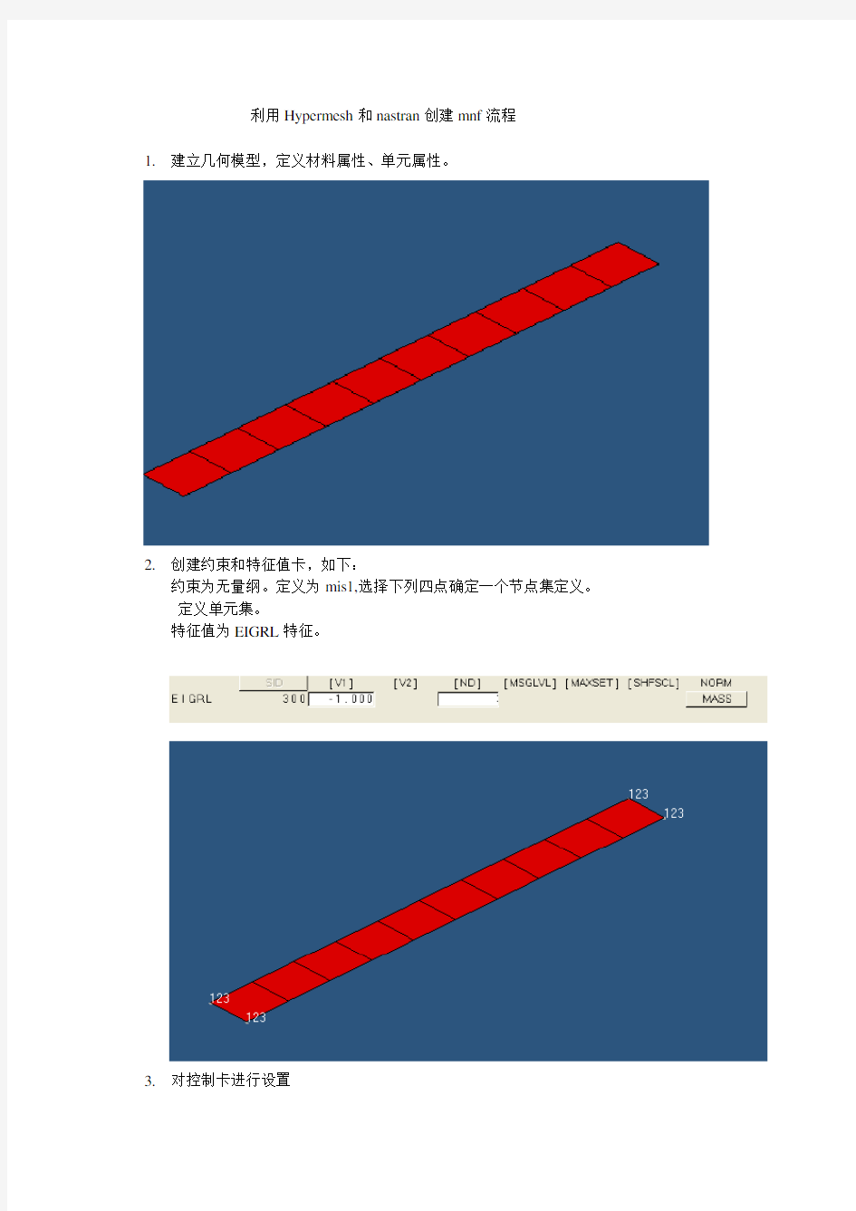
1.建立几何模型,定义材料属性、单元属性。
2.创建约束和特征值卡,如下:
约束为无量纲。定义为mis1,选择下列四点确定一个节点集定义。
定义单元集。
特征值为EIGRL特征。
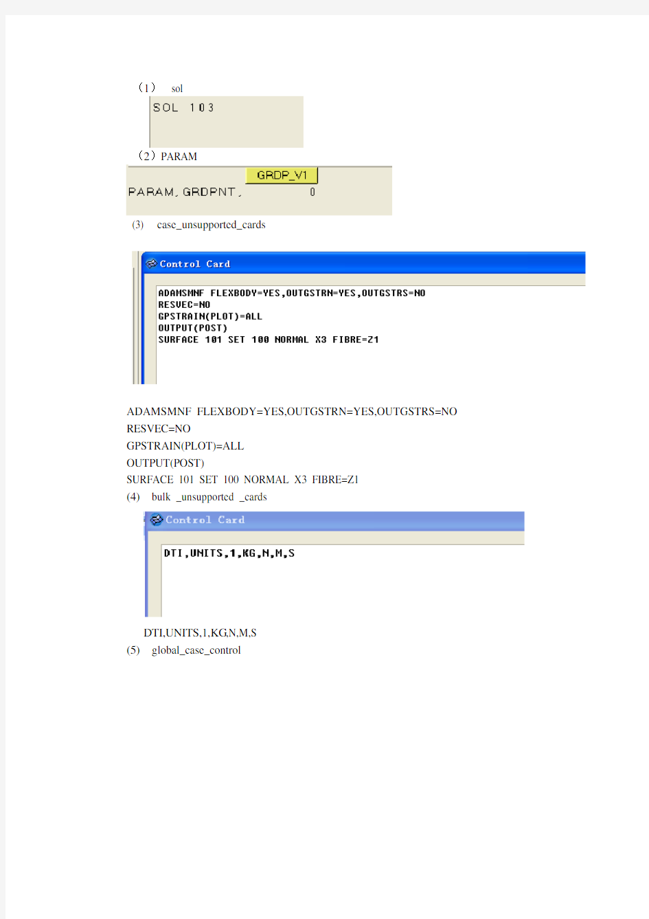
3.对控制卡进行设置
(1)sol
(2)PARAM
(3) case_unsupported_cards
ADAMSMNF FLEXBODY=YES,OUTGSTRN=YES,OUTGSTRS=NO RESVEC=NO
GPSTRAIN(PLOT)=ALL
OUTPUT(POST)
SURFACE 101 SET 100 NORMAL X3 FIBRE=Z1
(4)bulk _unsupported _cards
DTI,UNITS,1,KG,N,M,S
(5)global_case_control
Gpstress=all
相关文档; Translating MSC.Nastran Data
There are two different interfaces that you use to translate
MSC.Nastran data for use in ADAMS/Flex. Learn about:
? Using MSC.Nastran 2004 and Above ? Verifying the Model ? Computing Stress/Strain Modes ? XRB Support for Stress/Strain Modes ? Shortened Stress/Strain Modes
Using MSC.Nastran 2004 and Above
Starting in version 2004, MSC.Nastran provides an improved interface for generating modal neutral files (MNFs)
. The new MSC.Nastran ADAMS Interface allows you to generate an MNF directly from
MSC.Nastran without generating an OUTPUT2 file. The MSC.Nastran ADAMS Interface does not require a DMAP alter or a translator to convert MSC.Nastran output files to MNFs.
The MSC.Nastran ADAMS Interface is a licensed feature of
MSC.Nastran. For more information, contact your local sales representative. If you already have the MSC.Nastran ADAMS Interface license, refer to the MSC.Nastran Quick Reference Guide and Reference Manual for information on how to use it.
Verifying the Model
The MSC.Nastran translator writes a summary of the modal neutral file (MNF)export to the terminal window. If you are using
MSC.Nastran 2004 or above, the ADAMS interface writes a summary of the MNF export to the MSC.Nastran output file. Please review this data for any concerns. In particular, ensure that the:
?Mass, center of mass location, and moments of inertia are as expected.
?During the MNF write, the constraint modes and the constrained normal modes are orthogonalized. This yields modes that are: o An approximation of the free-body normal modes.
o Interface modes, where the interface is the collection of all the attachment point DOFs.
Also, verify that the free body normal modes have a reasonable natural frequency. You should expect to see six rigid-body modes, unless displacement boundary conditions are present.
Computing MSC.Nastran Stress/Strain
Modes
For ADAMS/Durability to process stresses or strains on flexible bodies, modal stress or strain shapes need to be present in the modal neutral file (MNF)of the flexible body. You do this by having MSC.Nastran
recover a stress or strain mode for every mode shape computed for Component Mode Synthesis (CMS).
?MSC.Nastran Grid Point Stresses
?Example
?Known Limitations, Problems, and Restrictions
MSC.Nastran Grid Point Stresses
Because modal information contained in the MNF can only be associated with nodes, the MSC.Nastran grid-point stress data recovery option is required. The following Case Control commands are required in the MSC.Nastran input file to compute stress or strain modes for the MNF:
?GPSTRESS: Requests grid point stresses output.
?GPSTRAIN: Requests grid point strains output.
?STRESS(PLOT): Requests element stress output.
?STRAIN(FIBER,PLOT): Requests element strain output.
?OUTPUT(POST): Delimiter.
?SET: Defines a set of elements for a surface or volume.
?SURFACE: Defines a surface of plate elements referenced by the SET command.
?VOLUME: Defines a volume of solid elements referenced by the SET command.
For more information on these commands, see the Case Control section of the MSC.visualNastran Quick Reference Guide. For more information on computing grid point stresses, see the MSC.Nastran Linear Static Analysis User's Guide.
Notes: You can only transfer one surface stress or strain fiber of plate elements to the MNF for processing in MSC.ADAMS. If more than one fiber is specified on the SURFACE card, the msc2mnf translator issues a warning message and only transfers the first surface stress fiber it finds in the OUTPUT2 file.
Including stress or strain modes in the MNF can significantly increase the file size. Therefore, it becomes even more important to optimize the MNF if possible. For information on optimizing the MNF, see Optimizing an MNF. Including both stress and strain modes will further increase the size of the MNF and is generally not recommended for large models, unless both quantities are needed. When defining subcases in Case Control, you must have the GPSTRESS, GPSTRAIN, STRESS, and STRAIN cards before the first SUBCASE card. In addition, the OUTPUT, SURFACE, and VOLUME cards should follow all subcase definitions and appear at the end of
the Case Control.
Example
This example shows the changes that are required in the MSC.Nastran input file when the computation and transfer of both stress and strain modes are desired. Because the model contains solid and shell elements, a surface and a volume are defined for computing these grid-point stresses and strains. The surface fiber selected is Z1 and the grid-point stress/strain coordinate system is consistently defined to be the basic FE model system.
Known Limitations, Problems, and Restrictions
?Only one FIBER is output on SURFACE.
?SURFACE or VOLUME should be defined in consistent coordinate (basic) system.
Example of Nastran for Stress and Strain
MSC.Nastran XDB Support for Stress/Strain Modes
You can store the ortho-normal stress and/or strain modes in XDB file format that are compatible with the mode shapes in the modal neutral file (MNF)and subsequent modal responses from an MSC.ADAMS
simulation. The benefits of this capability are:
?Unlimited model size - MSC.Patran can access results from an XDB file of any size and with much more efficiency than from an OP2 file.
?MSC.Fatigue analysis - Modal coordinates from MSC.ADAMS can be combined with stress or strain modes in XDB file for very efficient MSC.Fatigue analysis using modal superposition.
?Element-based support - The XDB file format supports element-based and/or grid-point based stress or strain.
Element-based results allow you to perform advanced fatigue
analyses such as multi-axial fatigue and weldments.
Learn more:
?Creating an XDB File
?Limitations
?Examples
Creating an XDB File
To create an XDB file with stress or strain modes, add the following entry in the Bulk Data section:
PARAM,POST,0
This is in addition to the necessary commands that are added to Case Control (see Computing MSC.Nastran Stress/Strain Modes). In the case of grid point stresses or strain, however, one additional command is required to output grid point stress or strain modes: STRFIELD = ALL
Note that if you are only interested in working with element-based stress or strain, this command is not needed. For more information on these entries and commands see the, MSC.Nastran Quick Reference Guide.
Back to top
Limitations
?Grid-point strain modes cannot be stored in the XDB nor can MSC.Patran post-process them.
?Element-based stress or strain modes cannot be stored in the MNF nor can ADAMS/Durability postprocess them.
Back to top
Examples
The following are examples of MSC.Nastran input decks. See the Case Control section of the MSC.Nastran Quick Reference Guide for more information on the ADAMSMNF command that is being used in these examples.
Example of Requesting No Grid Point Stress/Strain
In the following example, no grid point stress or strain modes have been requested. Only element-based strain modes have been requested with STRAIN(PLOT) = ALL. These strains will be stored in the XDB (PARAM,POST,0) for postprocessing in MSC.Patran or for combining with MSC.ADAMS modal responses from ADAMS/Durability for an MSC.Fatigue analysis. This is the most efficient process for obtaining strains for the sole purpose of performing a fatigue analysis. If you are not interested in viewing strains in MSC.ADAMS, there is no need to compute grid-point strain modes nor storing them in the MNF. You will also seea savings in file size and processing time from this. The same is true for stress modes if they are desired over strains. SOL 103
CEND
ADAMSMNF, FLEXBODY=YES, OUTGSTRS=NO, OUTGSTRN=NO
...
STRAIN(PLOT) = ALL
...
BEGIN BULK
...
PARAM,POST,0
...
ENDDATA
Example of Requesting Grid-Point Stress on All Solid Elements In the following example, grid-point stress (GPSTRESS) modes have been requested on all solid elements (VOLUME). This data, as well as the element-based stress (STRESS) modes, will be stored in the XDB due to the STRFIELD=ALL command and the PARAM,POST,0 card. The grid point stress modes will also be stored in the MNF with the OUTGSTRS=YES option set on the ADAMSMNF command. This allows ADAMS/Durability to postprocess stresses on the flexible body in MSC.ADAMS using the modal stress recovery technique.
SOL 103
CEND
ADAMSMNF, FLEXBODY=YES, OUTGSTRS=YES, OUTGSTRN=NO STRFIELD = ALL
...
STRESS(PLOT) = ALL
GPSTRESS = ALL
OUTPUT(POST)
SET 92 = ALL
VOLUME 12 SET 92 DIRECT
BEGIN BULK
...
PARAM,POST,0
...
ENDDATA
Example of Requesting Grid-Point Stress
In the following example, again, grid-point stress modes have been requested. They will not be stored in the XDB, however, because the STRFIELD=ALL command is missing. Therefore, only element-based stress modes will be available in the XDB. Grid-point stress modes will be stored in the MNF because the ADAMSMNF option, OUTGSTRS is still set to YES.
SOL 103
CEND
ADAMSMNF, FLEXBODY=YES, OUTGSTRS=YES, OUTGSTRN=NO
...
STRESS(PLOT) = ALL
GPSTRESS = ALL
OUTPUT(POST)
SET 92 = ALL
VOLUME 12 SET 92 DIRECT
BEGIN BULK
...
PARAM,POST,0
...
ENDDATA
Back to top
Shortened Stress/Strain Modes
Shortened stress/strain modes refers to the capability of defining a group or subset of elements in FEA for stress/strain recovery during modal neutral file (MNF)generation. FEA programs allow you to
judicially define subregions of your component where stress/strain is of interest. If these subregions are defined during MNF generation, the node length of the stress/strain modes becomes shorter than that for the mode shapes. This reduces the amount of stress/strain data in the MNF, and allows you to avoid doubling the file size when including stress or strain modes. ADAMS/Durability, however, will only be able to recover stress or strain at those subregions.
Support for this capability was first introduced in version 2005. Before 2005, a null tensor (all zero values) would be stored in the MNF for those nodes that did not have stress/strain computed by the FEA program. No reduction in file size was obtained, but worse yet, ADAMS/Durability would report zero stress/strain for those nodes, which could be misleading. In ADAMS/Flex 2005 or greater, it is now possible to remove these zero stress/strain states during MNF optimization. More information on how to do this is provided in the next sections.
Starting in MSC.Nastran 2005, only grid point stresses that are computed for a subset of the component are output to the MNF. Support for this capability by the other FEA programs is not yet available.
Learn more:
?Note on MNF Compatibility
?MNF Translation and Optimization
?Version Scenarios
Example
Note on MNF Compatibility
In general, an MNF is upward, but not necessarily backward, compatible. MSC.ADAMS will always support earlier versions of the MNF. For example, an MNF generated in a version of MSC.Nastran before 2005 will be supported. However, an MNF generated by MSC.Nastran 2005 or later will be incompatible in a version of MSC.ADAMS earlier than 2005. This is because, by default,
MSC.Nastran generates a version of the MNF that supports shortened stress/strain modes, or in other words, a reduced MNF. However, an option exists in ADAMS/Flex to convert a reduced MNF to a full MNF, so that it can be processed by earlier versions of MSC.ADAMS.
Back to top
MNF Translation and Optimization
Support for shortened stress/strain modes is available in the ADAMS/Flex MSC->MNF Translator and MNF->MNF Optimizer through the menu option Stress & Strain Modes. Three options are available as listed in the table below.
Example
In this MSC.Nastran example, ten shell elements (CQUAD4) are used to model a beam. Grid point strains are requested (GPSTRAIN) on
only four of the elements (4,5,6,7) because of the SET 100 specification on the SURFACE card. This results in a reduced MNF with shortened strain modes on grids that are common to those elements (grids 104 through 108 and 204 through 208).
SOL 103
CEND
$
ADAMSMNF FLEXBODY=YES,OUTGSTRN=YES,OUTGSTRS=NO
METHOD=300
RESVEC=NO
$
STRAIN(PLOT)=ALL
GPSTRAIN(PLOT)=ALL
OUTPUT(POST)
SET 100 = 4,5,6,7
SURFACE 101 SET 100 NORMAL X3 FIBRE=Z1
$
BEGIN BULK
ASET1,123,101,111,201,211
SPOINT,1001,thru,1003
QSET1,0,1001,thru,1003
DTI,UNITS,1,KG,N,M,S
PARAM,GRDPNT,0
$
EIGRL 300 -1. 3
$
GRID 101 0. 0. 0.
GRID 102 0.05 0. 0.
GRID 103 0.1 0. 0.
GRID 104 0.15 0. 0.
GRID 105 0.2 0. 0.
GRID 106 0.25 0. 0.
GRID 107 0.3 0. 0.
GRID 108 0.35 0. 0.
GRID 109 0.4 0. 0.
GRID 110 0.45 0. 0.
GRID 111 0.5 0. 0.
GRID 201 0. 0.03 0.
GRID 202 0.05 0.03 0.
GRID 203 0.1 0.03 0.
GRID 204 0.15 0.03 0.
GRID 205 0.2 0.03 0.
GRID 206 0.25 0.03 0.
GRID 207 0.3 0.03 0.
GRID 208 0.35 0.03 0.
GRID 209 0.4 0.03 0.
GRID 210 0.45 0.03 0.
GRID 211 0.5 0.03 0.
$
CQUAD4 1 1 101 102 202 201 CQUAD4 2 1 102 103 203 202 CQUAD4 3 1 103 104 204 203 CQUAD4 4 1 104 105 205 204 CQUAD4 5 1 105 106 206 205 CQUAD4 6 1 106 107 207 206 CQUAD4 7 1 107 108 208 207 CQUAD4 8 1 108 109 209 208 CQUAD4 9 1 109 110 210 209 CQUAD4 10 1 110 111 211 210 $
MAT1 1 2.+11 .3 7800. PSHELL 1 1 .01 1
ENDDATA
Hypermesh进行FLUENT前处理
Hypermesh 进行FLUENT 前处理 (2014-02-26 16:06:19) 转载▼ 标签: 分类: 网格生成技巧 杂谈 同属于ANSYS 阵营,ICEM CFD 及Tgrid 无疑是FLUENT 网格生成的良好选择。同时,作为 Workbench 平台的一个模块,利用 Mesh 为FLUENT 提供网格生成似乎也成了 ANSYS 的努力方 向。虽然说ICEM CFD ,TGRID 以及Mesh 都是非常优秀的网格生成工具,但是对于一些熟悉 Hypermesh 网格生成的人士来说,却并非是一种理想的选择,因为使用一款新的软件,意味着增加 新的学习成本。 FLUENT 网格生成包括两方面的内容,首先要将几何离散成网格,其次还应该包括边界命名。由于 在 FLUENT 中进行网格分割命名较为麻烦,因此这部分工作最好在网格生成之前进行。 Hypermesh 是Altair 公司的一款非常优秀的前处理工具,利用其可以为 FLUENT 生成网格。下面以 一个简单的例子来描述如何使用 Hypermesh 为FLUENT 生成网格。 1、启动 Hypermesh 启动Hypermesh ,进行User Profiles 对话框设置,选中 CFD ,如图所示。(这一设置不是必须的, 但是选中CFD 会有一些菜单提供快捷设置)。 2、导入几何模型 进入菜单【File 】 >【Import 】 >【Model 】如下图所示选择几何模型文件。点击 Import 按钮导入模 型。模型包含两个入口( inlet1及inlet2 )、一个岀口( outlet ),其他边界为壁面( wall )。
HyperMesh快捷键
HyperMesh常用快捷键及英文关键词 (2011-02-13 15:48:56) Hypermesh中常用快捷键 F1 -- Hidden Line 隐藏线 F2 -- Delete 删除(删除任何对象都用此命令) F3 -- Replace 合并两个节点 F4 -- Distance 测量距离,角度等 F5 -- Mask 隐藏 F6 -- Element Edit 单元编辑(创建,合并,分割单元等) F7 -- Align Node 节点共线排列 F8 -- Create Node 创建节点 F9 -- Line Edit 线编辑(非边界编辑) F10 -- Check Elem 单元质量检查 F11 -- collectors F12 -- Automesh 自动网格划分 Shift+F1-F12 Ctrl+F1-F6 Key Function key only plus SHIFT plus CTRL key F1 hidden line color print slide F2 delete temp nodes slide file F3 replace edges print eps (Note: Works only on UNIX) F4 distance translate eps file F5 mask find print b/w eps F6 element edit split JPEG file F7 align node project F8 create node node edit F9 line edit surf edit F10 check element normals F11 collectors organize F12 automesh smooth a arc 弧形 b back返回以前视图 c center
hypermesh常用命令
适合hypermesh初学者 常见英文解释 自己水平有限英语不太好自己总结适合初学者看看为了省钱方便浏览dangle 摇摆 Warpage 翘曲, 扭曲, 热变形 Aspect_Ratio 纵横比屏幕高宽比 Split v.劈开, (使)裂开, 分裂, 分离 n.裂开, 裂口, 裂痕 Tria Triaangle trigon n.三角形, ellipsoid n.椭圆体 project 投影计划实施 normals 法线 align node 对齐节点 b 返回以前视图 back z zoom p plot 刷新显示 w windows f fill r rotate c center t 设定视角显示 a arc 弧形 s slide 移动缩放 surfaces and faces 曲面和表面 duplicate adj.复制的 n.复制品 vt.复写, 复制 reject 否定拒绝 exponential 指数 tol tolerance 公差 mandatory 命令的, 强制的, 托管的 retrieve v.重新得到 n.找回 centroid n. 质心 trim adj. 整齐的, 整洁的 vt. 整理, 修整, 装饰 morph 变形 快捷键 F1 -- Hidden Line 隐藏线 F2 -- Delete 删除(删除任何对象都用此命令) F3 -- Replace 合并两个节点 F4 -- Distance 测量距离,角度等 F5 -- Mask 隐藏 F6 -- Element Edit 单元编辑(创建,合并,分割单元等) F7 -- Align Node 节点共线排列 F8 -- Create Node 创建节点 F9 -- Line Edit 线编辑(非边界编辑)
hypermesh前处理流程
1.选择求解器模版,如Ansys,Ls-Dyna,Nastran等 2.导入CAD模型,如ProE,UG等 3.几何清理 4.Mesh 网格划分可以从面网格开始,也可以从体网格开始。可以看看相关教程。 5.单元连接主要针对组件特别有用,可以看看我自己的总结 https://www.sodocs.net/doc/8910826510.html,/thread-838626-1-1.html https://www.sodocs.net/doc/8910826510.html,/304618/spacelist-blog-itemtypeid-1068 6.单元检查和修改 7.设置单元类型和材料 建议在ANSYS中设置,因为Hypermesh和ANSYS中的材料属性有些出入 这里要注意壳单元要设置单元的厚度,beam单元要设置界面信息 把这些设置完成后,设置Component相应属性的单元和材料及属性信息 8.清理单元 主要针对由面生成的体网格中含有的面单元的情况 9.(Optional,可选)设置边界和载荷,以及接触等 10.删除所有几何 11.导出FE模型 3~9项可以交叉进行(这是Hypermesh相对于其他前处理软件的优势) 要针对组件的连接,如焊接结构,铆接,杆状连接,铰接等等…… 可以用5种方法解决 1.接触 2.connect单元 1D、2D、3D都可以,里面有很多可以用的单元spot、seam、Bolt等 对于焊接单元spot、seam大多是求解器都支持,但是对于Bolt连接不一定,如Ansys就不支持
bolt在Ls-Dyna,Nastran,Hypermesh(default),radioss和OptiStruct(Hypermesh自带求解器)都能被支持在Nastran里,bolt的类型特别丰富,可以满足大多数需求 3.1D rigids(用于刚性连接,在其他求解器面板中可能为rbe2)rbe3(柔性单元),还有如beam,spring等 4.edges 融合相近的节点或者单元,容差tolerance一般设置为单元的大小的20%,超过这个值会引起单元畸形 5.单元来填充 单元之间的间隙大于单元大小 如果确实要连接间隙在单元大小20%~100%之间的节点或者单元,可以使用equilance来手动连接 只要你愿意,还有其他的很多方法,自己可以好好摸索
HyperMesh一些常见问题的解答
1、如何将.igs文件或.stl文件导入hypermesh进行分网? files\import\切换选项至iges格式,然后点击import...按钮去寻找你的iges文件吧。划分网格前别忘了清理几何 2、导入的为一整体,如何分成不同的comps?两物体相交,交线如何做?怎样从面的轮廓产生线(line)? 都用surface edit Surface edit的详细用法见HELP,点索引,输入surface edit 3、老大,有没有划分3D实体的详细例子? 打开hm,屏幕右下角help,帮助目录下hyperworks/tutorials/hyermesh tutorials/3D element,有4个例子。 4、如何在hypermesh里建实体? hm的几何建模能力不太强,而且其中没有体的概念,但它的曲面功能很强的.在2d面板中可以通过许多方式构建面或者曲面,在3D面板中也可以建造标准的3D曲面,但是对于曲面间的操作,由于没有"体"的概念,布尔运算就少了,分割面作就可以了 5、请问怎么在hypermesh中将两个相交平面到圆角啊? defeature/surf fillets 6、使用reflect命令的话,得到了映射的另一半,原先的却不见了,怎么办呢? 法1、在选择reflect后选择duplicate复制一个就可以 法2、先把已建单元organize〉copy到一个辅助collector中, 再对它进行reflect, 将得到的新单元organize〉move到原collector中, 最后将两部分equivalence, 就ok拉。 7、请问在hypermesh中如何划分装配体?比如铸造中的沙型和铸件以及冷铁, 他们为不同材质,要求界面单元共用,但必须能分别开? 你可以先划分其中一个部件,在装配面上的单元进行投影拷贝到被装配面上8、我现在有这样一个问题,曲线是一条线,我想把它分成四段,这样可以对每一段指定density,网格质量会比直接用一条封闭的线好。
Hypermesh中ANSYS模板基本操作流程
一、有限元模型(即“网格”)的组成 (1)网格 ①节点——提供“网格”的几何信息 ②材料——提供“网格”的材料特性参数 ③属性——提供“网格”的几何补充信息(例如:将薄板简化为二维网格(shell单元)时,需要对而二维网格(shell单元)补充薄板的“厚度信息”) 注:在hypermesh中“网格的几何补充信息”称为“属性(Property),并通过Property Collector完成属性的建立和管理;在Ansys中称作“实常数(Real Constans)”;在Hypermesh ANSYS模版中的Component Manager中也称为“实常数(Real Constans)”。 ④单元类型 小结:①②③④所提供的各种“网格”信息就创建出了“有限元网格模型”。 (2)当有限元模型带有边界条件时需要补充以下内容 ⑤载荷及边界条件 (3)做优化时需要补充以下内容 ⑥设计变量(Design Variable) ⑦响应(Response) 二、以上内容在Hypermesh中的创建步骤 步①:网格划分——即:完成“节点”的创建。 步②:在工具条中单击图标(Material Collector)打开“材料定义对话框”: 在对话框中自由指定材料名称,单击card image后面的输入框: 单击选择“Material”。单击“create/edit”,弹出“Meterial”卡片: 卡片中,DENS_FLAG为“密度”;EX_FLAG为“弹性模量”;NUXY_FLAG为“泊松比”,分别单击DENS_FLAG、EX_FLAG、NUXY_FLAG前边的,然后分别输入数值,如下所示: 注:中的数值“1”为ID号,默认即可,不用管它。 步③:在工具条中单击图标(Property Collector),弹
hypermesh常见问题解答
其实各种CAE前处理的一个共同之处就是通过拆分把一个复杂体拆成简单体。这个思路一定要记住,不要上来就想在原结构上分网,初学者往往是这个问题。刚开始学,day1,day2,advanced training 和HELP先做一遍吧。另外用熟24 个快捷键。 做一下HELP里面的教程,多了解一些基本的概念和操作。这样会快点入门。论坛更多的是方法。 划分的方法要灵活使用,再有就是耐心。 1、如何将.igs文件或.stl文件导入hypermesh进行分网? files\import\切换选项至iges格式,然后点击import...按钮去寻找你的iges 文件吧。划分网格前别忘了清理几何 2、导入的为一整体,如何分成不同的comps?两物体相交,交线如何做?怎样 从面的轮廓产生线(line)? 都用surface edit Surface edit的详细用法见HELP,点索引,输入surface edit 3、老大,有没有划分3D实体的详细例子? 打开hm,屏幕右下角help,帮助目录下hyperworks/tutorials/hyermesh tutorials/3D element,有4个例子。 4、如何在hypermesh里建实体? hm的几何建模能力不太强,而且其中没有体的概念,但它的曲面功能很强的.在2d面板中可以通过许多方式构建面或者曲面,在3D面板中也可以建造标准的3D 曲面,但是对于曲面间的操作,由于没有"体"的概念,布尔运算就少了,分割面作 就可以了 5、请问怎么在hypermesh中将两个相交平面到圆角啊? defeature/surf fillets 6、使用reflect命令的话,得到了映射的另一半,原先的却不见了,怎么办呢? 法1、在选择reflect后选择duplicate复制一个就可以 法2、先把已建单元organize〉copy到一个辅助collector中, 再对它进行reflect, 将得到的新单元organize〉move到原collector中, 最后将两部分equivalence, 就ok拉。 7、请问在hypermesh中如何划分装配体? 比如铸造中的沙型和铸件以及冷铁,他们为不同材质,要求界面单元共用,但必须能分别开? 你可以先划分其中一个部件,在装配面上的单元进行投影拷贝到被装配面上 8、我现在有这样一个问题,曲线是一条线,我想把它分成四段,这样可以对每一段指定density,网格质量会比直接用一条封闭的线好。
Hypermesh常用快捷键
Hypermesh中常用快捷键 ———————————————★—————————————————F1 -- Hidden Line 隐藏线 F2 -- Delete 删除(删除任何对象都用此命令) F3 -- Replace 合并两个节点 F4 -- Distance 测量距离,角度等 F5 -- Mask 隐藏 F6 -- Element Edit 单元编辑(创建,合并,分割单元等) F7 -- Align Node 节点共线排列 F8 -- Create Node 创建节点 F9 -- Line Edit 线编辑(非边界编辑) F10 -- Check Elem 单元质量检查 F11 -- collectors F12 -- Automesh 自动网格划分———————————————★—————————————————Shift+F1-F12 Ctrl+F1-F6
Key Function key only plus SHIFT plus CTRL key F1 hidden line color print slide F2 delete (删除) temp nodes slide file F3 replace edges print eps (Note: Works only on UNIX) F4 distance translate eps file F5 mask find print b/w eps F6 element edit split JPEG file F7 align node project F8 create node node edit F9 line edit surf edit F10 check element normals F11 collectors organize (move移动) F12 automesh smooth ————————————————★———————————————a arc 弧形 b back返回以前视图
Hypermesh总结-几何清理篇
Hypermesh总结-几何清理篇 1、geometry clean中出现的黄色边界线表示什么意思? 表示共享边,三个或者三个以上的面共同的边界 2、HM中有什么工具可以补面的? edit surface->surface filler 除了edit surface->surface filler外,还可以用spline,drag,sweep等命令补面,只要选surface only选项就可以了. 3、划好2d网格之后,用tool->edges->tolerance=0.01->equivalence->find edges, 最后发现220个free surfaces,我记得有一个快捷键保存这些自由面到内存中,然后可以删除刚刚保存的面,大侠,帮忙 用你的操作发现的是free edges,它会自动保存在一个叫做^edges的component里,然后隐藏掉其他的部分,再点击右侧QA-->Find Attached 找到相邻单元,再进行处理。 4、出现黄线怎么几何清除? GEOM CLEAN—SURFACE—FIND DUPLICATES试试 出现黄线大多是有重合面出现,结合隐藏(F5)仔细观察一下,找到重合的面(有的及其微小)删掉就是 5、2d单元划分完毕,在Tool->check elems->connectivity中发现有这样的提示:”574 elements were found with questionable connectivity“,这时有些单元高亮,怎么解决这个问题,使得没有单元有连接问题,大侠们指教! connectivity表示有重合单元存在,把重合单元删了就可以了。 具体操作如下:在Tool->check elems先点击duplicates,接着点击save failed;然后,按F2在elems下选retrieve,最后点击delete entity 6、体单元有什么优劣的评判指标; check elems/3-d面板中QI/Tool>.. 7、两个同心圆之间怎么生成填充曲面呢,两个圆都是红色的自由边界。 2D->spline 8、建模完后, find edges 检查没有通过,如何处理. 谢谢.请大家帮忙,方法是不是很多? disp里面隐掉其他comp,只显示free edge,在macro菜单里,选QA,选find attached,找到与此相关的失效单元,手工修改之。另外生成四面体还有检查T-connection,是不是不检查三维单元的free edges 和T-connection? 不用检查三维单元的T-connection,可以检查free edges 9、节点合并是哪个命令,在哪?单元的连续性是用这个吗? 可以用F3合并节点,注:当你选中equivalence的时候,是将两个节点合并为一个,没选的话,它们只是位置在一起,但还是两个节点.检查单元的连续性是tool_edge(也可用SHIFT+F3) edges(二维或曲面),faces(三维)单元连续性也用这个检查具体见练习:10、在检查三维实体单元节点一致的时候,先检查edges,再把三维实体单元生成表面(faces),然后再对生成的表面进行edges的检查。可以检查内部的节点。不知道这个方法有没有太多的问题,欢迎大家讨论! 对有的三维单元来说,先生成face再检查其edge,一般来说就可以了,但是如果当模型中如果内部有一个闭合的空心的话,检查face的edge是检查不出错误的,这时,要检查face 的法向,只有这样,才能真正的检查错误。如果不信的话,可以找一个无错误模型,删掉一个内部单元,再按上面的方法检查看一
hypermesh初学者常见问题汇总
.cn/topic_973849_1.html Hypermesh问题求助贴汇总和解答 1.请教哪位高手知道怎么把PROE图导入HYPERMESH 方法有很多,一是可以把模型直接导入hm里面,通过import 选择geo 再import即可,如果你的破衣文件版本比较低的话;二是可以将破衣文件另存为为stp或者igs格式,再在hm里面打开,这种方法比较常用和可靠,无论是你的破衣文件的版本有多高,它正常情况下(只要文件不是很大)都能打开。 2. HYPERMESH导入IGS模型出错 我用PRO/E建的模型,保存为IGS的文件,在HYPERMESH中导入的时候就会说产生一个分割错误,是否保存模型,确定后就说文件保存在crash0.hm,退出HYPERMESH。这是什么原因啊 导入几何图形出错有我知道的两种可能:一是上面所说的放在中文的文件夹里面,hm目前不能识别中文的文件夹;二是文件夹放在桌面也可能出错,最好还是放到某个盘里。 3. hyperMesh中的单元类型 请问HyperMesh中梁单元都有那些类型,怎样定义梁单元的截面属性. 在帮助文件能查找吗? 图片: 有很多类型:比如下面的图片那么多吧。在帮做里面能找到相关的资料,输入h,然后在索引里面输入beam即可找到相关内容 4. HM划分好的网格如何检查质量并对应自动修改? 请教各位,我在HM里面画好的网格,但是很多单元质量不符合后续处理的要求,提交模拟分析的时候老是报错,请问哪个命令可以自动找出这些问题网格,并自动修复,我是HM 最菜的菜鸟,烦请解释的说的详细些! 方法:先将不很你要求的网格找出来——————F10,检查你要求的质量,save failed。然后F5将合格的单元隐藏起来,在按一下Q,可以手动优化一下节点。但也可以直接用q来优化网格。 5. 兼容性问题 CATIA做出来的图能不能导入hypermesh9.0里分隔,如果能分完格的图能否用abaqus6.9分析? 可以。但可能不能直接将CATIA文件到hm里面,但可以另存为为另外的文件的格式,比如stp igs model等。Hm键catia文件画分完网格之后。可以直接在hm里面设置边界条件,再通过inp格式的文件导到abaqus6.9里面分析。 6. 求助各位大虾hypermesh中网格划分中的简单问题 各位大虾我在做hypermesh8.0例题HM3300时候,肋板网格划分完毕后,需要改变网格密度,正常是在下面单元密度输入需要的数目后点击网格上的数字就可以,但是我划分后,斜边上共8个节点,每个节点上都是数字1,而不是数字8,我怎么把斜边密度改成9呢?我想让斜边上只显示一个数字可以做到吗?
HyperMesh常用操作技巧[1]
HyperMesh常用操作技巧 0 HyperWorks软件难点常用词句中英文对比 Equivalenc:合并 Free Edge Filler Surface:缺失曲面自缝合 Circumference :圆周 Longitudinal:adj,纵向的,轴向的 Proceed:vi,继续 Criteria:n,标准 Batchmesher:网格划分批处理 Surface fillet midline split:曲面圆倒角中心线切割 Min feature angel:最小特征角 Element normal angel:法线角,用于控制单元间法线夹角的最大值 Tetramesh:四面体网格 Organize and cleanup fillets:圆倒角特征识别与几何清理 0-1 HyperWorks中的常用难点术语 1. 不完全分割面(Fin Faces):指面上所有边界均处于同一个实体内,或者说是独 立实体中的悬着面,默认呈现红色,可通过手动合并实体创建或使用内部悬着面创建实体的过程中创建; 2. 完全分割面(Full Partition Faces):指有一个或更多实体共享构成的边界面, 默认呈现黄色,切割实体或者使用布尔运算合并多个实体时在共享位置或交叉位置会产生完全分割面; 3. 边界面(Bounding Faces):指定义单一实体外边界的曲面,默认呈现绿色,边 界面是独立存在的并且不与其他实体所共有,一个独立的实体通常由多个边界面组成; 4.自由边(Free Edges):指被一个曲面所占用的边界,默认情况下显示红色。在仅由曲面构成的模型中,自由边将出现在模型的外缘和控内壁位置;相邻曲面间的自由边表示这两个曲面之间存在间隙,使用automesher时会自动保留
利用Hypermesh进行FLUENT前处理
用Hypermesh进行FLUENT前处理 同属于ANSYS阵营,ICEM CFD及Tgrid无疑是FLUENT网格生成的良好选择。同时,作为Workbench平台的一个模块,利用Mesh为FLUENT提供网格生成似乎也成了ANSYS的努力方向。虽然说ICEM CFD,TGRID以及Mesh都是非常优秀的网格生成工具,但是对于一些熟悉Hypermesh网格生成的人士来说,却并非是一种理想的选择,因为使用一款新的软件,意味着增加新的学习成本。 FLUENT网格生成包括两方面的内容,首先要将几何离散成网格,其次还应该包括边界命名。由于在FLUENT中进行网格分割命名较为麻烦,因此这部分工作最好在网格生成之前进行。 Hypermesh是Altair公司的一款非常优秀的前处理工具,利用其可以为FLUENT生成网格。下面以一个简单的例子来描述如何使用Hypermesh为FLUENT生成网格。 1、启动Hypermesh 启动Hypermesh,进行User Profiles对话框设置,选中CFD,如图所示。(这一设置不是必须的,但是选中CFD会有一些菜单提供快捷设置)。 2. 导入几何模型 进入菜单【File】>【Import】>【Model】如下图所示选择几何模型文件。点击Import 按钮导入模型。
导入的模型包含两个入口(inlet1及inlet2)、一个出口(outlet),其他边界为壁面(wall)。 3、创建Component 利用菜单【Mesh】>【Components】>【Create】或者在属性菜单Component上点右键创建四个Component放置面网格(inlet1,inlet2,outlet,wall),创建一个Component放置体网格(fluid)。创建完毕后的树形菜单如图所示。
Hypermesh补面及划分网格实用手册
Hypermesh补面及划分网格实用手册 作者:朱彦峰 2008年8月
第一章2Dmeshing 过程 Hyperworks (为有限元分析做前处理和后处理) —— Hypermesh : *为forge 提供的是#.nas 文件,2D 网格后的曲面。 使用步骤: 1打开hypermesh 软件后,在user profiles 菜单中选择hypermesh 和nastran ;或通过preferences 下拉菜单//user profiles 进行如上操作; 2选择files 设置输入文件的参数;将2处点开选择输入文件类型; 设置scale factor 和才leanup tol ;在选择import 输入文件。 3输入模型后: Organize >> collectors (给名;改变颜色;选择components ;和pshell 。 Shift+F11或Organize >> Entities (按surfs ,将选择的曲面copy 或移入该收集,作为参考);首先通过左上角model 树将新收集隐藏(在选hide 前应先选configure browser 一次,否则隐藏不了。 2 1 0.500
利用下面的工具进行放缩/移动和旋转等;(+、-可放缩); 可用 return 返回;利用3 处按钮控制模型是否着色显示;并设置Auto 到by 2D top ; 4 修补几何体: (1)Geom —— auto cleanup (2)利用 ,每次只勾选一个复选框,再利用 相互切换,同时运用Geom 状态下的各个工具修补曲面,消除红色和黄色边界线。 (edge edit —— (un )supress 可以删除锐角边,便于应力分析及meshing ;) 3
HyperMesh软件的基本操作
HyperMesh软件的基本操作 在HyperMesh中所有操作和命令都可以通过点击命令面板中的按钮实现,而通过键盘与鼠标的组合可以方便快捷的实现一些基本操作。熟练掌握以下介绍的这些操作可以在工作中节省很多时间。 一、模型的旋转与移动 二、键盘热键 热键操作 B 返回到以前操作的视图中 Z 缩放视图 P 刷新显示 W 窗口局部显示 F 充满窗口 R 旋转 C 设定视图中心 T 设定视角显示 A 弧形旋转 S 当鼠标上下移动时动态缩放视图 M 关闭菜单项,只显示图形(再按M回到菜单显示) +或- 逐步缩放视图 ↑←↓→逐步旋转视图 三、快捷键
功能键对应菜单加Shift键后的对应菜单加Ctrl键后的对应菜单F1 隐藏线(hidden line)颜色(color)打印幻灯片(print slide)F2 删除(delete)临时节点(temp nodes)幻灯片文件(slide file)F3 替代(replace)边(edges)打印EPS(只对UNIX系统)F4 距离(distance)移动(translate)EPS文件 F5 隐藏显示(mask)寻找(find)打印B/W EP3文件 F6 单元编辑(element edit)分割(split)JPEG文件 F7 节点对齐(align node)投影(project) F8 创建节点(create node)节点编辑(node edit) F9 编辑线(line edit)面编辑(surf edit) F10 检查单元(check element)法线(normal) F11 几何清理(quick edit)组织(organize) F12 自动划分网格(automesh)平滑(smooth) 在这里有一点需要说明的是,用快捷打开的命令在转变模型视图的时 候会自动退出,有些情况下我们需要在一个命令完成前变换视图方式, 在这种情况下就需要在命令面板中通过点击命令按钮来打开命令,而 不能用快捷键打开。如在用automesh命令时,我们有时需要通过0-D 与3-D转换来方便对所mesh面的选取。这时如果我们用快捷键F12 打开automesh命令,在3-D选取面后转换0-D时命令就会自动退出, 这样我们刚才选取面的工作就浪费了。而通过点击命令按钮来打开的 命令就不存在的问题,并且我们可以在这个命令上面叠加一个快捷键 打开的命令,而从面板打开的命令仍然可以保持原来的设置。也就是 说,通过点击命令按钮来打开的命令只要不点return退出,我们对这 个命令做的设置(如方向点,选取的单元)都会保持不变。我们也可 以利用这个特性方便我们的工作,在稍后的调节单元质量章节我们就 会用这个特性方便我们工作。读者朋友可以在今后的工作中灵活的运 用此特性。
hypermesh常见英文解释总结
HW英文翻译 dangle 摇摆 Warpage 翘曲, 扭曲, 热变形 Aspect_Ratio 纵横比屏幕高宽比 Split v.劈开, (使)裂开, 分裂, 分离 n. 裂开, 裂口, 裂痕 Tria Triaangle trigon n.三角形, ellipsoid n.椭圆体 project 投影计划实施 normals 法线 align node 对齐节点 b 返回以前视图 back z zoom p plot 刷新显示 w windows f fill r rotate c center t 设定视角显示 a arc 弧形 s slide 移动缩放 surfaces and faces 曲面和表面duplicate复制 reject 否定拒绝 tol tolerance 公差 mandatory 命令的, 强制的, 托管的retrieve v.重新得到 n.找回 centroid n. 质心 trim adj. 整齐的, 整洁的 vt. 整理, 修整, 装饰 morph 变形 exponential 指数 快捷键 F1 -- Hidden Line 隐藏线 F2 -- Delete 删除(删除任何对象都用此命令) F3 -- Replace 合并两个节点 F4 -- Distance 测量距离,角度等 F5 -- Mask 隐藏 F6 -- Element Edit 单元编辑(创建,合并,分割单元等) F7 -- Align Node 节点共线排列 F8 -- Create Node 创建节点 F9 -- Line Edit 线编辑(非边界编辑) F10 -- Check Elem 单元质量检查 F11 -- collectors F12 -- Automesh 自动网格划分
Hypermesh进行FLUENT前处理
Hypermesh进行FLUENT前处理 (2014-02-26 16:06:19) 转载▼ 分类:网格生成技巧 标签: 杂谈 同属于ANSYS阵营,ICEM CFD及Tgrid无疑是FLUENT网格生成的良好选择。同时,作为Workbench平台的一个模块,利用Mesh为FLUENT提供网格生成似乎也成了ANSYS的努力方向。虽然说ICEM CFD,TGRID以及Mesh都是非常优秀的网格生成工具,但是对于一些熟悉Hypermesh网格生成的人士来说,却并非是一种理想的选择,因为使用一款新的软件,意味着增加新的学习成本。 FLUENT网格生成包括两方面的内容,首先要将几何离散成网格,其次还应该包括边界命名。由于在FLUENT中进行网格分割命名较为麻烦,因此这部分工作最好在网格生成之前进行。Hypermesh是Altair公司的一款非常优秀的前处理工具,利用其可以为FLUENT生成网格。下面以一个简单的例子来描述如何使用Hypermesh为FLUENT生成网格。 1、启动Hypermesh 启动Hypermesh,进行User Profiles对话框设置,选中CFD,如图所示。(这一设置不是必须的, 但是选中CFD会有一些菜单提供快捷设置)。 2、导入几何模型 进入菜单【File】>【Import】>【Model】如下图所示选择几何模型文件。点击Import按钮导入模型。模型包含两个入口(inlet1及inlet2)、一个出口(outlet),其他边界为壁面(wall)。
3、创建Component 利用菜单【Mesh】>【Components】>【Create】或者在属性菜单Component上点右键创建四个Component放置面网格(inlet1,inlet2,outlet,wall),创建一个Component放置体网格(fluid)。创建完毕后的树形菜单如图所示。 4、面网格划分 利用快捷键F12进行面网格划分,注意设置相应Component为Current。划分完毕后的网格如图所示。(可以使用shift+F11快捷键移动网格至相应的component)
如何学Hypermesh
如何学Hypermesh Hypermesh是目前综合功能最强大的有限元前处理器之一。 总有朋友问很多关于Hypermesh的问题,结合我个人的使用经验,写下这篇文章随便谈谈,不一定都对,如果有不同意见,欢迎切磋。 问题1:Hypermesh很难学么?从哪里开始学? 不难,不仅不难,而且很简单,简单到什么地步?如果有人在旁边稍微指点你一下,你只要不是特别笨,通过1,2天的实战训练,你就能掌握大部分常用的功能。当然,这里说的是划分网格的功能,不包括求解器。 刚开始学,一定要选一本(或几本)好的资料,这个资料就是day1,day2,高级培训和帮助文件里的手册。好的资料要多都几遍,对基本概念和基本操作都有一个整体的把握,把基础打好。 2:Hypermesh划分网格时的核心思想是什么? 一句话:为了得到单元,可以不择手段。 受到其他有限元软件划分网格思想的束缚,初学者往往被几何模型本身束缚了手脚,在HM中,几何的作用仅仅是为了得到网格,得到了网格之后,几何就可以扔到垃圾堆里面了。 为了得到网格的方便,你可以随心所欲地分割几何面,几何体,而不必担心会把几何弄坏了而造成什么不良影响。为了划分网格的需要,你可以随意添加辅助线,辅助面,不必担心自己添加进来的线,面会有什么不良影响。 为了得到网格,你可以把一些不重要的特征线toggle掉,当它不存在。
要记住:只要能得到网格,其他的都不重要。当然了,网格的几何位置,必须要和几何匹配,不然得到的单元就不能反映原有几何的特征了。 我的建议: 学习过程,我也走了不少弯路,自己总结一下,主要有两点:一,资料很多,但是自己不要贪多,hypermesh中几个经典的案例在网上,或者自带的help 中都有,也就几个,重复的做,不嫌烦的做,把那几个常用的命令搞熟透,掌握了上面基本的操作之后,自己摸索着不看帮助的做;二、针对项目,或者一个新的模型,自己按照自己的思路做,与别人交流。第一步的话我觉得一周时间足矣掌握,后面的虽然你可以搞定,但是要做好的话,就需要积累了。 百度里面搜索“极速有限元”,可以找到Hypermesh最经典的资料,也欢迎大家跟我交流。
使用Hypermesh前处理做abaqus静态的步骤
在HYPERMESH中使用Abaqus(Standard3D)模板计算带接触的静态 一、导入三维模型→模型清理→薄板件采用壳单元&铸件采用体单元 说明:体单元做法 A做法很多:、 B介绍tetramesh: ●要先将每个面进行2d网格划分,形成封闭网格,才能选择这个部件进行“tetra mesh”。可以用三角网格。 ●Volume tetra:必须将部件进行切割成很多Mappable块,画出来为6面体单元。 ●对于关注件采用2阶单元:采用进行阶次转换。 二、创建材料 三、创建属性 Type=line/planar/nodal/solid… 四、创建接触(若有)
●Analysis->Interface下创建主面、从面、接触对; ●给主面、从面add elements\surface_node\csurf等。其中csuf可以通过Analysis->contactsurfs 创建。 ●Contact pair及Contact Pair property的设置参考如下: Contact_Pair 设置Contact_Property 设置 说明:Adjust 用来调整初始间距;SurfaceBehavior中的Exponential用来指定初始接触压力,方便收敛,如下图示 五、创建螺栓及施加预紧力 ●用梁单元模拟螺栓时,单个螺栓的梁单元要超过3个单元数 ●Utility->Contact Manager 的interface 界面下:”new”-“pre tension section”,选择梁单元中间的某个单元,输入预 紧力大小,”create”-“apply”-“OK” 六、载荷与边界
HYPERMESH入门指南
仿真在线提供 https://www.sodocs.net/doc/8910826510.html, 作者 yidixunmeng 简明目录 第一章INTRUCTION 第二章永久菜单 第三章macro菜单 第四章Geom面板 第五章2D/3D面板 第六章tools面板 第七章一些画网格的例子 第一章 INTRUCTION HYPERMESH是一个非常强大的前处理软件,当然它的其它功能也很有用,但是我们通常只用它来划网格。可惜的是有关他的书籍或者教程特别的少。我作的这个指南主要是用来解释以及演示一下它的各个子面板的用法和一些个人的看法,其中也有一些我自己的经验。希望对大家有用。当然这些面板的用法在help文件里面都有,只是都是英文的,给我们广大的非常喜欢hm的朋友造成了一定困难。所以我作了这个,希望大家喜欢。当然由于水平原因,其中可能会有这样或那样的错误,在这里我衷心的希望大家能给与批评指正。 第二章永久菜单 永久菜单在面板上是不变化的,无论你选哪个面板,他都在屏幕的右下角。这里面的一些用法很重要。 Z—zoom的缩写,就是缩放的意思。当你import一个图形,你想仔细看图形的某个部分,这时你就可以点击永久菜单上的Z来进行图形缩放,点击一次之后再你需要放大的地方画 一个圆形,这样在圆中的部分就被放大了。效果如下:
P—相当于refresh,就不多说了。 R—rotate 旋转点击R之后,将鼠标放在屏幕上,点击左键,图形就会自动旋转。 F—fit 拟和和 ug等cad软件的用法一样。 C—center 点击这个键之后,随便在屏幕上点击一下左键,整个屏幕将以这个点为圆心重新布置。 S—也是放大或缩小,点击S之后,在屏幕上按住鼠标左键上下拖动,图形就放大或缩小。 是旋转,点击之后,按住左键移动,图形就会转动。 View—在day1,中day2有详细介绍,就不多说了。
Hypermesh前处理建模技巧
随堂笔记 硬点:几何上面的点 point 每天下午四点准时把当天所画模型发一份过来进行反馈 节点:网格上的点 n ode 组件管理器 部件管理器 当前层 建模第一步 抽中面 比较薄的钣金件都在中面上面画壳网格 第三步 清理几何 常用快捷键 ■□曲B lriQ$ rpickMt nods edit li ■日 sdrl s-uiifcDa edit solid 日日? H'iqa adit 1日呷rodes lenflth 勺睢助JTE point edit dstinDe Ed :ztecB dirtocleariuo 窗 Geoni 广 to 广 2D r 30 r Anar ;'=.i5 r Ttiiol r Posd f *心世t 世人-丨翼匕 自 y Lafp ODir's di7iei&c p ji ng
清理几何的要求 容差:简单理解是给定给电脑的一个搜索范围值
通过两个硬点创建线 split surf-node: node node spirt surHine: node line 令 washer split. line(s) offset value: 0.100 unsplit surf: line(s) toggle sdge. line(s) tolerance: 0.100 tiller surf line(s) delete surf: surffsj 只能删除自己增加的边界线,原有的边界线不能操作 Washer :只在螺栓孔上做,为了模拟垫片的受力情况 split surf-norie: split surf-line: washer split: unsplit surf: toggle edge : filler surf: dolete surf: node nodes ■A nade lines ■ lirtefs) offset value: | 0 . 10 0 line(s) line(s) tolerance: | 0 1 0 0 lins(s) surffs) 通过一个硬点创建一条垂直于所选线的直线
相关文档
- hypermesh 绝对精品教程 力荐
- HYPERMESH入门指南
- hyperworks_hypermesh_HYPERMESH讲义
- HyperMesh&LS-DYNA控制卡片
- (完整版)hypermesh常用面板及快捷键
- HyperMesh入门教程
- hypermesh-绝对精品教程-力荐
- hypermesh常用快捷键及英文关键字
- hypermesh常用命令
- Hypermesh前处理建模技巧
- Hypermesh常用快捷键
- HyperMesh常用操作技巧[1]
- 第三章用Tcl执行HyperMesh的命令介绍
- Hypermesh分析设定解析
- Hypermesh常用快捷键
- Hypermesh补面及划分网格实用手册
- 如何学Hypermesh
- hypermesh快捷键及常见英文
- HyperMesh快捷键
- HyperMesh常用操作技巧[1]