flat optics controlling wavefronts with optical antenna metasurfaces
Flat Optics:Controlling Wavefronts With
Optical Antenna Metasurfaces
Nanfang Yu,Member,IEEE,Patrice Genevet,Francesco Aieta,Mikhail A.Kats,Romain Blanchard,Member,IEEE, Guillaume Aoust,Jean-Philippe Tetienne,Zeno Gaburro,and Federico Capasso,Fellow,IEEE
(Invited Paper)
Abstract—Conventional optical components rely on the propa-gation effect to control the phase and polarization of light beams. One can instead exploit abrupt phase and polarization changes associated with scattered light from optical resonators to control light propagation.In this paper,we discuss the optical responses of anisotropic plasmonic antennas and a new class of planar op-tical components(“metasurfaces”)based on arrays of these an-tennas.To demonstrate the versatility of metasurfaces,we show the design and experimental realization of a number of?at optical components:1)metasurfaces with a constant interfacial phase gra-dient that de?ect light into arbitrary directions;2)metasurfaces with anisotropic optical responses that create light beams of arbi-trary polarization over a wide wavelength range;3)planar lenses and axicons that generate spherical wavefronts and nondiffracting Bessel beams,respectively;and4)metasurfaces with spiral phase Manuscript received August26,2012;revised January8,2013;accepted January12,2013.Date of publication January21,2013;date of current version April25,2013.This work was supported in part by the Harvard Nanoscale Sci-ence and Engineering Center under contract NSF/PHY06-46094,in part by the Center for Nanoscale Systems at Harvard University,which is a member of the National Nanotechnology Infrastructure Network,and in part by the Defense Advanced Research Projects Agency(DARPA)N/MEMS S&T Fundamentals program under Grant N66001-10-1-4008issued by the Space and Naval War-fare Systems Center Paci?c.The work of P.Genevet was supported by the Robert A.Welch Foundation(A-1261).The work of M.A.Kats was supported by the National Science Foundation through a Graduate Research Fellowship. The work of Z.Gaburro was supported by the European Communities Seventh Framework Programme(FP7/2007-2013)under Grant PIOF-GA-2009-235860. N.Yu was with the School of Engineering and Applied Sciences,Harvard University,Cambridge,MA02138USA.He is now with the Department of Applied Physics and Applied Mathematics,Columbia University,New York, NY10027USA(e-mail:ny2214@https://www.sodocs.net/doc/8c14578824.html,).
P.Genevet is with the School of Engineering and Applied Sciences,Har-vard University,Cambridge,MA02138USA,and also with the Institute for Quantum Studies and Department of Physics,Texas A&M University,College Station,TX77843USA(e-mail:pgenevet@https://www.sodocs.net/doc/8c14578824.html,).
F.Aieta,M. A.Kats,R.Blanchard,and F.Capasso are with the School of Engineering and Applied Sciences,Harvard University,Cambridge, MA02138USA(e-mail:faieta@https://www.sodocs.net/doc/8c14578824.html,;mikhail@https://www.sodocs.net/doc/8c14578824.html,; blanchar@https://www.sodocs.net/doc/8c14578824.html,;capasso@https://www.sodocs.net/doc/8c14578824.html,).
G.Aoust was with the School of Engineering and Applied Sciences,Harvard University,Cambridge,MA02138USA,and also with Ecole Polytechnique, Palaiseau91128,France.He is now with The French Aerospace Lab,ON-ERA,Palaiseau91120,France(e-mail:gaoust@https://www.sodocs.net/doc/8c14578824.html,).
J.-P.Tetienne was with the School of Engineering and Applied Sciences,Har-vard University,Cambridge,MA02138USA.He is now with Laboratoire de Photonique Quantique et Mol′e culaire,Ecole Normale Sup′e rieure de Cachan and CNRS,Cachan94235,France(e-mail:jean-philippe.tetienne@ens-cachan.fr). Z.Gaburro is with the School of Engineering and Applied Sciences,Har-vard University,Cambridge,MA02138USA,also with the Dipartimento di Fisica,Universit`a degli Studi di Trento,Trento38100,Italy(e-mail: gaburro@https://www.sodocs.net/doc/8c14578824.html,).
Color versions of one or more of the?gures in this paper are available online at https://www.sodocs.net/doc/8c14578824.html,.
Digital Object Identi?er10.1109/JSTQE.2013.2241399distributions that create optical vortex beams of well-de?ned or-bital angular momentum.
Index Terms—Antenna arrays,lenses,metamaterials,optical polarization,optical surface waves,phased arrays.
I.I NTRODUCTION
T HE general function of most optical devices can be de-scribed as the modi?cation of the wavefront of light by altering its phase,amplitude,and polarization in a desired man-ner.The class of optical components that alter the phase of light waves includes lenses,prisms,spiral phase plates[1],axi-cons[2],and more generally spatial light modulators(SLMs), which are able to imitate many of these components by means of a dynamically tunable spatial phase response[3].A second class of optical components such as waveplates utilizes bulk birefrin-gent crystals with optical anisotropy to change the polarization of light[4].A third class of optical components such as grat-ings and holograms is based on diffractive optics[5],where diffracted waves from different parts of the components inter-fere in the far-?eld to produce the desired optical pattern.All of these components shape optical wavefronts using the propa-gation effect:the change in phase and polarization is gradually accumulated during light propagation.This approach is gener-alized in transformation optics[6],[7]which utilizes metama-terials to engineer the spatial distribution of refractive indices and,therefore,bend light in unusual ways,achieving phenom-ena such as negative refraction,subwavelength focusing,and cloaking[8],[9].
It is possible to break away from our reliance on the prop-agation effect,and attain new degrees of freedom in molding the wavefront and in optical design by introducing abrupt phase changes over the scale of the wavelength(dubbed“phase dis-continuities”)into the optical path.This can be achieved by us-ing the large and controllable phase shift between the incident and scattered light of resonant optical scatterers,assembled in suitable arrays as proposed in[10].Their arrangement should satisfy two requirements,subwavelength thickness of the array and subwavelength separation of the scatterers,i.e.,the array must form a metasurface.The choice of optical scatterers is potentially wide ranging including nanoparticles[11],nanocav-ities[12],[13],nanoparticles clusters[14],[15],optical anten-nas[16],[17],and dielectric resonators such as nanocrystals or quantum dots[18].In this paper,we concentrate on recent devel-opments in this area that have focused on the use of planar op-tical antennas as resonators,due to the widely tailorable optical properties and the ease of fabrication of these nanoscale-thick
1077-260X/$31.00?2013IEEE
metallic structures.This approach has led to the design and
demonstration of a new class of planar optically thin photonic
devices such as optical phased arrays that can re?ect and re-
fract light into practically arbitrary directions[10],[19]–[21],
optical vortex plates[10],[22],perfect propagating-wave-to-
surface-wave converters[23],and?at lenses and axicons[24].
In addition,it has been shown that spatially varying polariza-
tion manipulation produces a geometrical phase modi?cation
closely related to the Pancharatnam–Berry phase[25],[26],
which modi?es the wavefront of the transmitted beam[27]–[33].
By an appropriate design of anisotropic optical antennas,one
can also introduce abrupt polarization changes as light is trans-
mitted or re?ected by the metasurface.Metasurfaces with gi-
ant optical birefringence have been demonstrated[34]–[39].
Finally by tailoring the spatial pro?les of the phase disconti-
nuities and polarization,response across the metasurface novel
background-free and broad-band quarter-wave plates have been
demonstrated[40].
This paper presents a systematic study of the properties of
plasmonic antennas in changing the phase and polarization of
the scattered light,and the applications of plasmonic antenna
arrays in?at optical components(“metasurfaces”).Optical an-
tennas are optical analogs of radiowave antennas.They have
a wide range of potential applications[41]–[53].Previous re-
search efforts have primarily focused on the capability of op-
tical antennas in capturing and concentrating light power into
subwavelength regions[54]–[58].However,their phase and po-
larization responses and their implications in controlling the
propagation of light have not been systematically investigated.
This paper is organized as follows.Section II discusses the
fundamental optical properties of plasmonic antennas,includ-
ing the basics of antenna resonance,eigenmodes of anisotropic
antennas,and scattering properties of phased optical antenna
arrays.Section III presents a few applications of metasur-
faces comprising phased optical antenna arrays.These include
demonstration of generalized laws of re?ection and refraction,
broadband background-free plasmonic wave plates,planar plas-
monic lenses,and phase plates that generate optical vortices.
Section IV gives conclusion.
II.P HASE AND P OLARIZATION R ESPONSES
OF O PTICAL A NTENNAS
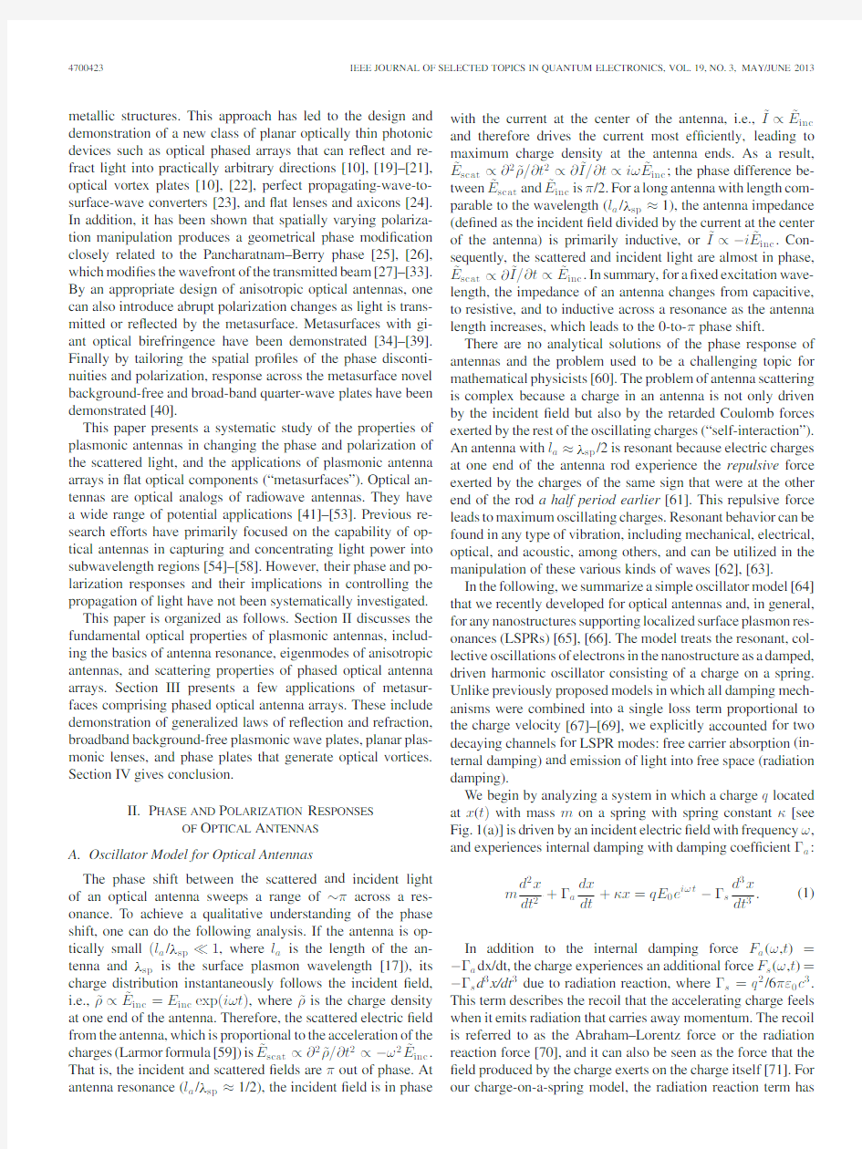
A.Oscillator Model for Optical Antennas
The phase shift between the scattered and incident light
of an optical antenna sweeps a range of~πacross a res-
onance.To achieve a qualitative understanding of the phase
shift,one can do the following analysis.If the antenna is op-
tically small(l a/λsp 1,where l a is the length of the an-tenna andλsp is the surface plasmon wavelength[17]),its
charge distribution instantaneously follows the incident?eld,
i.e.,?ρ∝?E inc=E inc exp(iωt),where?ρis the charge density
at one end of the antenna.Therefore,the scattered electric?eld
from the antenna,which is proportional to the acceleration of the
charges(Larmor formula[59])is?E scat∝?2?ρ/?t2∝?ω2?E inc. That is,the incident and scattered?elds areπout of phase.At antenna resonance(l a/λsp≈1/2),the incident?eld is in phase with the current at the center of the antenna,i.e.,?I∝?E inc and therefore drives the current most ef?ciently,leading to maximum charge density at the antenna ends.As a result,?E
scat∝?2?ρ/?t2∝?
?I/?t∝iω?E
inc
;the phase difference be-tween?E scat and?E inc isπ/2.For a long antenna with length com-parable to the wavelength(l a/λsp≈1),the antenna impedance (de?ned as the incident?eld divided by the current at the center of the antenna)is primarily inductive,or?I∝?i?E inc.Con-sequently,the scattered and incident light are almost in phase,?E
scat∝?
?I/?t∝?E
inc
.In summary,for a?xed excitation wave-length,the impedance of an antenna changes from capacitive, to resistive,and to inductive across a resonance as the antenna length increases,which leads to the0-to-πphase shift.
There are no analytical solutions of the phase response of antennas and the problem used to be a challenging topic for mathematical physicists[60].The problem of antenna scattering is complex because a charge in an antenna is not only driven by the incident?eld but also by the retarded Coulomb forces exerted by the rest of the oscillating charges(“self-interaction”). An antenna with l a≈λsp/2is resonant because electric charges at one end of the antenna rod experience the repulsive force exerted by the charges of the same sign that were at the other end of the rod a half period earlier[61].This repulsive force leads to maximum oscillating charges.Resonant behavior can be found in any type of vibration,including mechanical,electrical, optical,and acoustic,among others,and can be utilized in the manipulation of these various kinds of waves[62],[63].
In the following,we summarize a simple oscillator model[64] that we recently developed for optical antennas and,in general, for any nanostructures supporting localized surface plasmon res-onances(LSPRs)[65],[66].The model treats the resonant,col-lective oscillations of electrons in the nanostructure as a damped, driven harmonic oscillator consisting of a charge on a spring. Unlike previously proposed models in which all damping mech-anisms were combined into a single loss term proportional to the charge velocity[67]–[69],we explicitly accounted for two decaying channels for LSPR modes:free carrier absorption(in-ternal damping)and emission of light into free space(radiation damping).
We begin by analyzing a system in which a charge q located at x(t)with mass m on a spring with spring constantκ[see Fig.1(a)]is driven by an incident electric?eld with frequencyω, and experiences internal damping with damping coef?cientΓa:
m
d2x
dt2
+Γa
dx
dt
+κx=qE0e iωt?Γs
d3x
dt3
.(1)
In addition to the internal damping force F a(ω,t)=?Γa dx/dt,the charge experiences an additional force F s(ω,t)=?Γs d3x/dt3due to radiation reaction,whereΓs=q2/6πε0c3. This term describes the recoil that the accelerating charge feels when it emits radiation that carries away momentum.The recoil is referred to as the Abraham–Lorentz force or the radiation reaction force[70],and it can also be seen as the force that the ?eld produced by the charge exerts on the charge itself[71].For our charge-on-a-spring model,the radiation reaction term has
YU et al.:FLAT OPTICS:CONTROLLING W A VEFRONTS WITH OPTICAL ANTENNA METASURFACES
4700423
Fig.1.(a)Optical antenna can be modeled as a charged harmonic oscillator, where q is the charge and m is the inertial mass.(b)Schematics for FDTD sim-ulations.A gold optical antenna(length L=1μm,thickness t=50nm,and width w=130nm)lies on a silicon substrate and is illuminated by a normally incident plane wave polarized along the antenna axis.The cross represents a point~4nm away from the antenna edge where the near-?eld is calculated. The complex permittivity of gold is taken from[72].(c)Upper panel:scattering σscat and absorptionσab s cross sections,and near-?eld intensity as calcu-lated via the oscillator model(solid curves)and FDTD simulations(dashed curves).The scattering and absorption cross sections are de?ned asσscat(ω) =P scat(ω)/I0andσab s(ω)=P ab s(ω)/I0,where I0is the incident intensity.
A total-?eld/scattered-?eld plane-wave source was employed in FDTD simula-tions to extract the scattered power P scat(ω)and absorbed power P ab s(ω)of the antenna.Lower panel:oscillator phase(solid curve)and the phase of the near-?eld calculated via FDTD(dashed curve).
to be included for physical consistency,and cannot be absorbed into the internal damping coef?cientΓa.
By assuming harmonic motion x(ω,t)=x(ω)e iωt,it follows from(1)that
x(ω,t)=
(q/m)E0
(ω20?ω2)+iωm(Γa+ω2Γs)
e iωt=x(ω)e iωt(2)
whereω0=
k/m.The time-averaged absorbed power by the
oscillator can be written as P abs(ω)=F a(ω,t)?(iωx(ω,t)), where F a(ω,t)?is the complex conjugate of the internal damp-ing force.Similarly,the time-averaged scattered power by the oscillator is P scat(ω)=F s(ω,t)?(iωx(ω,t)).Therefore,we have
P abs(ω)=ω2Γa|x(ω)|2(3)
P scat(ω)=ω4Γs|x(ω)|2.(4) Our oscillator model can shed light on the relationship be-tween the near-?eld,absorption,and scattering spectra in op-tical antennas.If we interpret the optical antenna as an os-cillator that obeys(1)–(4),we can associate P abs and P scat in(3)and(4)with the absorption and scattering spectra of the antenna,respectively.Furthermore,we can calculate the near-?eld intensity enhancement at the tip of the antenna as |E near(ω)|2∝|x(ω)|2[69].
By examining(3)and(4)and noting that P scat∝ω2P abs∝ω4|E near(ω)|2,we can deduce that the scattering spectrum P scat(ω)will be blue-shifted relative to the absorption spectrum P abs(ω),which will in turn be blue-shifted relative to the near-?eld intensity enhancement spectrum|E near(ω)|2.This is in agreement with experimental observations that the wavelength dependence of near-?eld quantities such as the electric-?eld enhancement can be signi?cantly red-shifted compared with far-?eld quantities such as scattering spectra[73]–[78].These spectral differences can also be clearly seen in?nite-difference time-domain(FDTD)simulations of gold linear antennas on a silicon substrate designed to resonate in the midinfrared spec-tral range[see Fig.1(c)].We?t the simulation results presented in Fig.1(c)with(3)and(4)to obtain the parameters q,m,ω0, andΓa.The resulting model is able to explain the peak spectral position and general shape of the near-?eld intensity,as well as the phase response of the antenna[see Fig.1(c)].This result suggests that this model can predict the near-?eld amplitude and phase response from experimental far-?eld spectra of antennas, which are much easier to obtain than near-?eld measurements. Our model shows that in LSPR systems the near-?eld,absorp-tion,and scattering spectra are all expected to peak at different frequencies and have distinct pro?les.
It is important to note that our results remain valid only for wavelengths far enough away from any material resonances. For example,in the visible range near an interband transition for gold the absorption spectrum for nanospheres peaks at a smaller wavelength than the scattering spectrum[78],contrary to the predictions of our model.It appears that our model can be safely applied to noble metal structures in the near-and midinfrared spectral range and longer wavelengths.To treat the short wavelength regime,our model could be augmented by introducing an additional oscillator with a coupling term to represent the resonant absorption due to an interband transition in a metal[65].
B.Eigenmodes of Anisotropic Plasmonic Antennas
To gain full control over an optical wavefront,we need a subwavelength optical element able to span the phase of the scattered light relative to that of the incident light from0to 2πand able to control the polarization of the scattered light.A plasmonic element consisting of two independent and orthogo-nally oriented oscillator modes is suf?cient to provide complete control of the amplitude,phase,and polarization response,and is,therefore,suitable for the creation of designer metasurfaces as described in detail in[39]and[79].
A large class of plasmonic elements can support two orthog-onally orientated modes.We focus on lithographically de?ned nanoscale V-shaped plasmonic antennas as examples of two-oscillator systems[10],[39],[79],[80].The antennas consist
4700423IEEE JOURNAL OF SELECTED TOPICS IN QUANTUM ELECTRONICS,VOL.19,NO.3,MAY/JUNE2013 Fig.2.(a)V-shaped optical antenna is a simple example of a plasmonic two-oscillator element.Its two orthogonal modes,i.e.,symmetric and antisymmetric modes,are shown,respectively,in the left and right panels.The schematic current distribution on the antenna is represented in gray scale with lighter tones indicating larger current density.The instantaneous direction of current?ow is indicated by arrows with gradient.(b)SEM images of gold V-shaped antennas fabricated on a silicon substrate with opening anglesΔ=45?,75?,90?,and120?.(c)–(e)Measured transmission spectra through the V-antenna arrays at normal incidence as a function of wavelength and angleΔfor?xed arm length h=650nm.Transmission here is the ratio of the transmitted intensity to that through the bare Si substrate to account for multiple re?ections in the latter.The polarization of the incident light is indicated in the upper-right corners.(f)–(h)FDTD simulations corresponding to the experimental spectra in(c)–(e),respectively.The feature betweenλo=8and9μm is due to the phonon resonance in the~2nm SiO2on the substrate.
of two arms of equal length h connected at one end at an angle Δ.They support“symmetric”and“antisymmetric”modes[see Fig.2(a)],which are excited by electric?elds parallel and per-pendicular to the antenna symmetry axes,respectively.In the symmetric mode,the current and charge distributions in the two arms are mirror images of each other with respect to the an-tenna’s symmetry plane,and the current vanishes at the corner formed by the two arms(see Fig.2(a),left panel).This means that,in the symmetric mode,each arm behaves similarly to an isolated rod antenna of length h,and therefore the?rst-order antenna resonance occurs at h≈λsp/2.In the antisymmetric mode,antenna current?ows across the joint(see Fig.2(a),right panel).The current and charge distributions in the two arms have the same amplitudes but opposite signs,and they approxi-mate those in the two halves of a straight rod antenna of length 2h.The condition for the?rst-order resonance of this mode is,therefore,2h≈λsp/2.The experiments and calculations in Fig.2(c)–(h)indeed show that the two modes differ by about a factor of2in resonant wavelength.Systematic calculations of the current distributions of the symmetric and antisymmetric modes as a function of the antenna geometry are provided in [79].Most importantly,the phase response of the scattered light from a V-antenna covers the range from0to2π,as opposed to theπrange of a linear antenna,since it results from the ex-citation of a linear combination of the two antenna modes for arbitrarily oriented incident polarization[10],[39],[79].This full angular coverage makes it possible to shape the wavefront of the scattered light in practically arbitrary ways.
The scattered light largely preserves the polarization of the incident?eld when the latter is aligned parallel or perpen-dicular to the antenna symmetry axis,corresponding to unit vectors?s and?a,respectively[see Fig.2(a)].For example, when the incident light is polarized along the?s direction, the scattered electric?eld is polarized primarily along the same axis since the charge distribution is primarily dipolar. Note that a quadrupolar mode is excited in the?a direction but its radiative ef?ciency is poor.For an arbitrary incident polarization,both the symmetric and antisymmetric antenna modes are excited,but with substantially different amplitudes and phases due to their distinctive resonance conditions.As a result,the antenna radiation can have tunable polarization states.
YU et al.:FLAT OPTICS:CONTROLLING W A VEFRONTS WITH OPTICAL ANTENNA METASURFACES4700423
TABLE I
A NTENNA S CATTERED F IELD
We characterized the spectral response of V-antennas by
Fourier transform infrared(FTIR)spectroscopy and numerical
simulations.In Fig.2,we mapped the two oscillator modes of
V-antennas as a function of wavelength and opening angleΔ
by showing the measured(c)–(e)and calculated(f)–(h)trans-
mission spectra.The gold antennas fabricated on silicon wafers
have arm length h=650nm,width w=130nm,thickness t=
60nm,and opening angle ranging from45?to180?.Fig.2(c)and
(f)corresponds to excitation of only the x-oriented symmetric
antenna mode,whereas(d)and(g)corresponds to the y-oriented
antisymmetric mode,and(e)and(h)shows both excited modes.
The spectral positions of these resonances are slightly differ-
ent from the?rst-order approximation which would yieldλx≈2hn e?≈3.4μm andλy≈4hn e?≈6.8μm,taking n e?as 2.6[10],with the differences attributed to the?nite aspect ratio
of the antennas and near-?eld coupling effects.The latter are
especially strong for smallΔwhen the arms are in closer prox-
imity to each other,leading to a signi?cant resonance shift[see
Fig.2(d)and(g)].All of the experimental results are reproduced
very well in simulations,including the feature at8–9μm due
to a phonon resonance in the2-nm native silicon oxide layer
on the silicon substrate,which is enhanced by the strong near-
?elds formed around the metallic antennas.In Fig.2(d),(e),(g),
and(h),a higher order antenna mode is clearly visible atλo≈2.5μm for largeΔ.
C.Design of a Phased Optical Antenna Array
The essence of metasurfaces is to use spatially inhomoge-neous arrays of anisotropic optical antennas to control optical wavefronts.As an example,we designed a set of eight different V-antennas(see Table I),which provide phase shifts over the entire0-to-2πrange in increments ofπ/4and are used as basic elements for constructing metasurfaces.The?rst four antennas in the array have their symmetry axes oriented along the same direction.The last four antennas are obtained by rotating the ?rst four antennas in the clockwise direction by90?.It will be shown later that this coordinate transformation introduces aπphase shift in the scattered light of the last four antennas.
We follow three steps to calculate the scattered light from the antennas as shown in Table I.First,the incident?eld with an arbitrary linear polarization is decomposed into components along the?s and?a axes,which will excite the two eigenmodes, respectively.Second,we calculate the complex scattered?elds of the eigenmodes(S i?s and A i?a,i=1–4),which can be obtained by analytical calculations or simulations[10],[39],[79].Third, the scattered?eld of the i th antenna and its rotated counterpart is expressed as a linear combination of the?eld components radiated by the symmetric and antisymmetric modes,in the x–y reference frame,as shown in the last row of Table I.Equation (5)provides explicitly the expressions for the?elds scattered by the eight antennas:
?
??
??
??
??
??
??
??
E
1
E
2
E
3
E
4
E
5
E
6
E
7
E
8
?
??
??
??
??
??
??
??
=
1
2
?
??
??
??
??
??
??
??
S1?A1
S2?A2
S3?A3
S4?A4
?(S1?A1)
?(S2?A2)
?(S3?A3)
?(S4?A4)
?
??
??
??
??
??
??
??
cos(2β?α)?y
+sin(2β?α)?x
+
1
2
?
??
??
??
??
??
S1+A1
S2+A2
S3+A3
S4+A4
S1+A1
S2+A2
S3+A3
S4+A4
?
??
??
??
??
??
cosα?y
+sinα?x
.(5)
Here,the anglesαandβrepresent the orientation of the incident?eld and of the antenna symmetry axis,respectively. Equation(5)shows that the scattered light from the antennas ( E i,with i=1–8)contains two terms,which are polarized along the(2β?α)-direction and theα-direction,respectively. Note that the minus signs of the(2β?α)-polarized components of antennas5–8originate from the rotation of the antenna sym-metry axis.
We spatially tailor the antenna geometries so that atλ= 8μm the(2β?α)-polarized components of all the antennas have the same amplitudes and phase increments ofΔΦ=π/4 [see Fig.3,and Fig.4(a)and(b)].That is,|S i–A i|is con-stant,with i=1–4,and Phase(S i+1–A i+1)–Phase(S i–A i) =π/4,with i=1–3.Therefore,the(2β?α)-polarized partial waves scattered from the antenna array form an extraordinary beam propagating away from the surface normal.On the other hand,theα-polarized components,which have the same po-larization as the incident light,have similar phase responses at λ=8μm[see Fig.4(c)].Therefore,they combine to form a wave that propagates along the surface normal and contributes to an ordinary beam.Note that one has independent control of the wavefronts and polarizations of the two beams:the wave-fronts are determined by the complex scattering amplitudes S i and A i,which are in turn determined by antenna materials and geometries(i.e.,arm length h,opening angleΔ,arm width,
4700423IEEE JOURNAL OF SELECTED TOPICS IN QUANTUM ELECTRONICS,VOL.19,NO.3,MAY/JUNE2013 Fig.3.(a)and(b)Calculated amplitude and phase of the x-polarized component of the scattered light,E scat,x,for gold V-antennas with different geometries atλ=8μm.The incident?eld is polarized along the y-axis(α=0?)and the antenna symmetry axis is along45?direction(β=45?);therefore the scattered ?eld E scat,x is cross-polarized with respect to the incident light(2β?α=90?as shown by the?rst term on the right-hand side of(5)).We chose four antennas indicated by circles in(a)and(b)so that they provide nearly equal scattering amplitudes and incremental phases ofπ/4for the cross-polarized scattered?eld E scat,x.(c)FDTD simulations of E scat,x for individual antennas.The antennas are excited by y-polarized plane waves with the same phase.The difference in the propagation distance of wavefronts emanated from neighboring antennas is1μm,corresponding to a phase difference ofπ/4.
thickness of metal);the polarizations are instead controlled by the orientation angles of the incident?eld and the antenna sym-metry axis(i.e.,αandβ).In most of the device applications of metasurfaces to be discussed in Section III,we choose antenna orientationβ=45?and vertical incident polarizationα=0?, so the(2β?α)-polarized component is in cross polarization.
III.A PPLICATIONS OF P LASMONIC M ETASURFACES
A.Generalized Laws of Re?ection and Refraction
In this section,we show one of the most dramatic demon-strations of controlling light using metasurfaces;that is,a linear phase variation along an interface introduced by an array of phased optical antennas leads to anomalously re?ected and re-fracted beams in accordance with generalized laws of re?ection and refraction.We note that antenna arrays in the microwave and millimeter-wave regime have been used for the shaping of re?ected and transmitted beams in the so-called re?ectarrays and transmitarrays[81]–[85].There is a connection between that body of work and our work in that both use abrupt phase changes associated with antenna resonances.However,the gen-eralization of the laws of re?ection and refraction we are going to present is made possible by the deep-subwavelength thick-ness of our optical antennas and their subwavelength spacing.It is this metasurface nature that distinguishes it from re?ectarrays and transmitarrays,which typically consist of a double-layer structure separated by a dielectric spacer of?nite thickness,and the spacing between the array elements is usually not subwave-length.
To derive the generalized laws of re?ection and refraction, one can consider the conservation of wavevector(i.e.,k-vector) along the interface.Importantly,the interfacial phase gradient dΦ/dr provides an effective wavevector along the interface that is imparted onto the transmitted and re?ected photons.Consider the2-D situation in Fig.5(a),where the phase gradient dΦ/dx lies in the plane of incidence.Wavevector conservation states that the sum of the tangential component of the incident wavevector, k o n i sin(θi),and dΦ/dx should equal the tangential component of the wavevector of the refracted light,k o n t sin(θt).From this simple relation,one can derive that
sin(θt)n t?sin(θi)n i=
1
k o
dΦ
dx
.(6)
Equation(6)implies that the refracted beam can have an arbitrary direction in the plane of incidence,provided that a suitable constant gradient of phase discontinuity along the in-terface dΦ/dx is introduced[10].Because of the nonzero phase gradient in this modi?ed Snell’s law,the two angles of incidence
YU et al.:FLAT OPTICS:CONTROLLING W A VEFRONTS WITH OPTICAL ANTENNA METASURFACES
4700423
Fig.4.(a)and (b)Full-wave simulations of the phase and amplitude of scattered light with cross polarization,E scat ,x ,for an array of eight gold V-antennas in the wavelength range λ=5–16μm.The geometries of the ?rst four antennas in the array are indicated in Fig.3(a);the last four antennas are obtained by rotating the ?rst four antennas 90?clockwise.(c)and (d)Full-wave simulations of the phase and amplitude of the y -polarized component of the scattered light,E scat ,y ,in the wavelength range λ=5–16μm.All phases are referred to the phase of antenna 1,which is taken to be 0.In all the plots,antenna 9is the same as 1.
±θi lead to different values for the angle of refraction.As a con-sequence,there are two possible critical angles for total internal re?ection,provided that n t θc =arcsin ±n t n i ?1k o n i d Φ dx .(7) Similarly,for the re?ected light we have sin (θr )?sin (θi )= 1k o n i d Φ dx . (8) There is a nonlinear relation between θr and θi ,which is dra-matically different from conventional specular re?ection.Equa-tion (8)predicts that there is always a critical incidence angle θ c =arcsin 1? 1k o n i d Φdx (9)above which the re?ected beam becomes evanescent. In the 3-D situation with arbitrary orientation of the interfacial phase gradient,one has to consider separately the conservation of wavevector parallel and perpendicular to the plane of inci-dence [see Fig.5(b)].For the transmitted light beam,we have ?????k x,t =k x,i + d Φdx k y ,t =k y ,i +d Φdy (10) where k x,t =k o n t sin(θt )and k x,i =k o n i sin(θi )are the in-plane wavevector components of the refracted and incident beams,respectively;k y ,t =k o n t cos(θt )sin(?t )and k y ,i =0are the out-of-plane wavevector components of the refracted and inci-dent beams,respectively.Therefore,(10)can be rewritten as ?????n t sin (θt )?n i sin (θi )= 1k o d Φdx cos (θt )sin (?t )=1n t k o d Φ dy (11) which is the generalized law of refraction in 3-D [20].Similarly,the generalized law of re?ection in 3-D reads ?????sin (θr )?sin (θi )= 1n i k o d Φdx cos (θr )sin (?r )=1n r k o d Φdy .(12) The ?rst equations in (11)and (12)are the same as the 2-D situation (See (6)and (8)).The out-of-plane de?ection angles ?t and ?r are determined by the out-of-plane phase gradient d Φ/dy . The interfacial phase gradient originates from inhomoge-neous plasmonic structures on the interface and it provides an extra momentum to the re?ected and transmitted photons.In return,the photons should exert a recoil force to the interface.Note that the generalized laws (see (6),(8),(11),and (12))can also be derived following Fermat’s principle (or the principle of stationary phase)[10],[20].The latter states that the total phase shift Φ( r s )+ B A k o n ( r )dr accumulated must be station-ary for the actual path a light beam takes.Here,the total phase shift includes the contribution due to propagation B A k o n ( r )dr 4700423IEEE JOURNAL OF SELECTED TOPICS IN QUANTUM ELECTRONICS,VOL.19,NO.3,MAY/JUNE 2013 Fig.5.(a)Schematics used to derive the2-D generalized Snell’s law.The interface between the two media is arti?cially structured to introduce a constant phase gradient dΦ(x)/dx in the plane of incidence,which serves as an effective wavevector that de?ects the transmitted beam.The generalized law is a result of wavevector conservation along the interface.(b)In the3-D situation,the phase gradient dΦ/dr does not lie in the plane of incidence and wavevector conservation occurs in both the x-and y-directions.In particular,the out-of-plane phase gradient dΦ/dy gives rise to out-of-plane refraction and re?ection. and abrupt phase changesΦ( r s)acquired when the light beam transverses an interface; r s is the position along the interface. By using the eight V-antennas described in Table I as building blocks,we created metasurfaces that imprint a linear distribu-tion of phase shifts to the optical wavefronts.A representative fabricated sample with the highest packing density of antennas is shown in Fig.6(a).A periodic antenna arrangement with a constant incremental phase is used here for convenience,but is not necessary to satisfy the generalized laws.It is only nec-essary that the phase gradient is constant along the interface. The phase increments between nearest neighbors do not need to be constant,if one relaxes the unnecessary constraint of equal spacing between neighboring antennas. Fig.6(b)shows the schematic setup used to demonstrate the generalized https://www.sodocs.net/doc/8c14578824.html,rge arrays(~230μm×230μm)were fabri-cated to accommodate the size of the plane-wave-like excitation with a beam radius of~100μm.A buried-heterostructure quan-tum cascade laser(QCL)with a central wavelength of8μm and a spectral width of~0.2μm was used as the light source.The laser beam was incident from the backside of the silicon wafer,which was not decorated with antennas.The sample was mounted at Fig.6.(a)SEM image of a metasurface consisting of a phased optical an-tenna array fabricated on a silicon wafer.The metasurface introduces a linear phase distribution along the interface and is used to demonstrate the generalized laws of re?ection and refraction.The unit cell of the structure(highlighted) comprises eight gold V-antennas of width~220nm and thickness~50nm and it repeats with a periodicity ofΓ=11μm in the x-direction and1.5μm in the y-direction.The antennas are designed so that their(2β–α)-polarized components of the scattered waves have equal amplitudes and constant phase differenceΔΦ=π/4between neighbors.FDTD simulations show that the scat-tering cross sectionsσscat of the antennas range from0.7to2.5μm2,which are comparable to or smaller than the average area each antenna occupies,σaver (i.e.,the total area of the array divided by the number of antennas).Therefore, it is reasonable to assume that near-?eld coupling between antennas introduces only small deviations from the response of isolated antennas.Simulations also show that the absorption cross sectionsσab s are approximately?ve to seven times smaller thanσscat,indicating comparatively small Ohmic losses in the antennas at midinfrared wavelength range.(b)Schematic experimental setup for y-polarized excitation(electric?eld normal to the plane of incidence)and phase gradient in the plane of incidence.Beams“0,”“1,”“2,”and“3”are ordinary refraction,extraordinary refraction,extraordinary re?ection,and or-dinary re?ection,respectively;γindicates the angular position of the detector. (c)Experimental far-?eld scans showing the ordinary and extraordinary refrac-tion generated by metasurfaces with different interfacial phase gradients(from 2π/13to2π/17μm?1)at different wavelengths(from5.2to9.9μm),given normally incident light.This broadband response is independent of the incident polarization.The scans are normalized with respect to the intensity of the or-dinary beams.At a wavelength of7.7μm,the intensity of the extraordinary refraction is30–40%of that of the ordinary beams,corresponding to~10%of the total incident power.The arrows indicate the calculated angular positions of the extraordinary refraction according toθt=–arcsin(λ/Γ).(d)Calculated far-?eld intensity distribution(|E|2)as a function of wavelength for a metasurface withΓ=15μm.We used a dipolar model in which V-antennas are replaced by dipolar emitters with phase and amplitude responses speci?ed in Fig.4.The dashed curve is analytical calculation according toθt=–arcsin(λ/Γ).The cir-cles represent the angular positions of the extraordinary beams extracted from experimental data in(c).(e)Ratio between the left and the right half of(d) to show the relative intensity between the extraordinary refraction atθt=–arcsin(λ/Γ)and the parasitic diffraction atθt=arcsin(λ/Γ)as a function of wavelength. YU et al.:FLAT OPTICS:CONTROLLING W A VEFRONTS WITH OPTICAL ANTENNA METASURFACES 4700423 Fig.7.(a)Measured far-?eld intensity as a function of the angular position γof the detector [de?ned in Fig.6(b)]at different angles of incidence θi .The unit cell of the metasurface has a lateral periodicity of Γ=15μm.Beams “0,”“1,”“2,”and “3”correspond to those labeled in Fig.6(b).The very weak beams “4”and “5”originate from the second-order diffraction of the antenna array of periodicity Γ.Their nonzero intensity is due to imperfections in the antenna array (i.e.,slight mismatch in scattering amplitudes and deviation from a linear phase distribution).At θi =4.3?beam “2”cannot be measured in our setup because it is counterpropagating with respect to the incident beam.(b)Measured far-?eld intensity pro?les with a polarizer in front of the detector.The polarizer ?lters the scattered light that is cross-polarized with respect to the incident light.(c)Angle of refraction versus angle of incidence for the ordinary and extraordinary refraction for the sample with Γ=15μm.The curves are theoretical calculations using the generalized Snell’s law (6)and the symbols are experimental data.The two arrows indicate the modi?ed critical angles for total internal re?ection.The red symbols correspond to negative angle of refraction.(d)Angle of re?ection versus angle of incidence for the ordinary and extraordinary re?ection for the sample with Γ=15μm.The inset is the zoom-in view.The curves are theoretical calculations using (8)and the symbols are experimental data.The arrow indicates the critical incidence angle above which the anomalously re?ected beam becomes evanescent.The red symbols correspond to negative angle of re?ection. the center of a motorized rotation stage,and a liquid-nitrogen-cooled mercury–cadmium–telluride (MCT)detector positioned ~15cm away from the sample was scanned to determine the angular positions of the two ordinary beams and the two ex-traordinary beams.Our measurements were performed with an angular resolution of 0.2?. Fig.6(c)shows the experimental far-?eld scans at excitation wavelengths from 5.2to 9.9μm.Three samples with Γ=13,15,and 17μm were tested.For all samples and excitation wave-lengths,we observed the ordinary and extraordinary refraction and negligible optical background.Samples with smaller Γcre-ate larger phase gradients and,therefore,de?ect extraordinary refraction into larger angles from the surface normal;smaller Γalso means a higher antenna packing density and,therefore,more ef?cient scattering of light into the extraordinary beams [see Fig.6(c)].The observed angular positions of the extraor-dinary refraction agree very well with the generalized law of refraction,θt =–arcsin(λ/Γ)(6). The antenna arrays can provide phase coverage from 0to 2πwith an increment of ~π/4over a wide range of wavelengths [see Fig.4(a)].Therefore,the metasurface can generate well-de?ned extraordinary refraction over a broad spectral range,which is con?rmed in experiments [see Fig.6(c)].This broad-band performance can be understood by referring to the phase plot in Fig.3(b).The latter is calculated for a ?xed wavelength of 8μm.Increasing (decreasing)the operating wavelength is equivalent to scaling down (up)the size of the antennas,or mov-ing the circles representing antenna geometries in the diagram downward (upward).Within a certain range of the movement,the circles sample the linear distribution of the phase plot [see 4700423IEEE JOURNAL OF SELECTED TOPICS IN QUANTUM ELECTRONICS,VOL.19,NO.3,MAY/JUNE2013 Fig.3(b)];therefore,the relative phase between the antennas is maintained.That is why the antenna designs are quite robust against wavelength change. The broadband performance of the metasurface is further demonstrated in Fig.6(d)and(e).The ratio between the intensity of extraordinary refraction at?arcsin(λ/Γ)and that of the parasitic diffraction at arcsin(λ/Γ)is in excess of a few hundred betweenλ=8μm and10μm[see Fig.6(e)].In this optimal wavelength range,the cross-polarized component of the scattered?eld across the antenna array maintains a linear phase response and a relatively uniform amplitude response[see Fig.4(a)and(b)].Away from the optimal range,the scattering amplitude into the cross-polarization decreases and its variation increases[see Fig.4(b)],but the linear phase response is still well maintained[see Fig.4(a)].This leads to reduced intensity in the extraordinary refraction and reduced suppression ratio [see Fig.6(c)and(e)].The value of is still above10atλ=5 and14μm. The strong suppression of diffraction at the angle ?arcsin(λ/Γ)compared to arcsin(λ/Γ)illustrates the difference between our metasurface and a conventional diffractive grating with periodΓwhere light is equally diffracted at positive and negative orders.In fact,the high suppression ratio means that the structure operates functionally as a blazed grating where light is preferentially diffracted into a single order[5].We have veri?ed both experimentally and numerically that this also holds true for noncoplanar refraction[20].Larouche and Smith have in fact established the formal equivalence between the generalized law of refraction[10]and diffraction from a blazed grating[86]. However,there is a fundamental difference in the way the phase of the scattered light is controlled in metasurfaces with a con-stant phase gradient compared to a blazed grating.In the latter, it is governed by optical path differences between light scattered by grating grooves with a sawtooth pro?le(i.e.,a propagation effect),whereas in our optically thin plasmonic interface,it is controlled by abrupt phase shifts(phase discontinuities)since light scatters off deeply subwavelength thick optical antennas. An important consequence of this is that our metasurface is broadband in contrast to conventional blazed gratings.Finally, we wish to point out that by symmetry considerations there is no intensity at the zero diffraction order(θt=0?)in cross po-larization in our metasurfaces because the complex amplitude of the cross-polarized light scattered by the four antennas(i= 1–4in Table I)is exactly canceled by the amplitude scattered by the other four antennas,since they are the mirror images of the ?rst four when antenna orientationβ=45?.The light measured atθt=0?is the ordinary refraction polarized as the incident radiation. For a complete characterization of the metasurfaces,we changed the incident angleθi and scanned the detector over a larger angular range to capture both the extraordinary refrac-tion and re?ection.The experimental far-?eld scans for a sample withΓ=15μm atλ=8μm are shown in Fig.7(a).A polar-izer was added between the sample and the detector to isolate cross-polarized extraordinary beams and the results are shown in Fig.7(b).The intensity of the extraordinary refraction(beams “1”)is about one-third of that of the ordinary refraction(beams Fig.8.Experimental observation of out-of-plane refraction.Angles of refrac-tionθt and?t[de?ned in Fig.5(b)]versus angles of incidence for a phase gradient perpendicular to the plane of incidence.Angle?t represents the angle between the extraordinary refraction and the plane of incidence and it is propor-tional to the out-of-plane interfacial phase gradient dΦ/dy.The experimental data,3-D generalized Snell’s law,and FDTD simulations are in good agreement.“0”).Atλ=8μm the metasurface scatters approximately10% of the incident light into the extraordinary refraction and approx-imately15%into the extraordinary re?ection.The ef?ciency can be increased by using denser antenna arrays or by exploiting an-tenna designs with higher scattering amplitudes(e.g.,antennas with a metallic back plane operating in re?ection mode). Fig.7(c)and(d)shows the angles of refraction and re?ec-tion,respectively,as a function of incident angleθi for both the silicon–air interface and the metasurface with linear interfacial phase gradient.In the range ofθi=0–9?,the cross-polarized extraordinary beams exhibit negative angle of refraction and re-?ection[see the red curves in Fig.7(a)and(b),and red circles in Fig.7(c)and(d)].The critical angle for total internal re?ection is modi?ed to about–8?and+27?for the metasurface in accor-dance with(7)compared to±17?for the silicon–air interface [see Fig.7(c)];the anomalous re?ection does not exist beyond θi=–57?[see Fig.7(d)]. We demonstrated out-of-plane refraction(see Fig.8)in accor-dance with the3-D generalized law[(11)]using the same meta-surface patterned with phased optical antenna arrays shown in Fig.6(a)oriented in such a way that the interfacial phase gradi-ent forms a nonzero angle with respect to the plane of incidence [see Fig.5(b)].Because of the tangential wavevector provided by the metasurface,the incident beam and the extraordinary re-?ection and refraction are in general noncoplanar.The extraor-dinary beams’direction can be controlled over a wide range by varying the angle between the plane of incidence and the phase gradient,as well as the magnitude of the phase gradient. B.Broadband Metasurface Wave Plate Considerable attention has been drawn to the optical proper-ties of assemblies of anisotropic metallic and dielectric struc-tures,which can mimic the polarization-altering characteris-tics of naturally occurring birefringent and chiral media.Planar YU et al.:FLAT OPTICS:CONTROLLING W A VEFRONTS WITH OPTICAL ANTENNA METASURFACES4700423 Fig.9.(a)Measurements and(b)FDTD simulations of the cross-polarized scattering for the V-antenna arrays in Fig.2(b).The arrows indicated the polar-izations of the incident and output light.As expected,the polarization conversion peaks in theλ=3–8μm range,in the vicinity of the two antenna eigenmodes shown in Fig.2.The peak polarization conversion ef?ciency is about15%. chiral metasurfaces change the polarization state of transmitted light to a limited degree[87]–[92].Circular polarizers based on 3-D chiral metamaterials primarily pass light of circular polar-ization of one handedness while the transmission of light of the other handedness is suppressed(circular dichroism)[93],[94]. Because of the dif?culty of fabricating thick chiral metamate-rials,the demonstrated suppression ratio between circular po-larizations of different handedness is quite small(<10).One way to overcome this dif?culty is to use planar structures com-prising strongly scattering anisotropic particles that are able to abruptly change the polarization of light.V-antennas are one example[10],[20]–[22],[24],[39],[79],[80];other exam-ples include arrays of identical rod or aperture metallic anten-nas[34]–[38],[95],[96]or meander-line structures[97]–[99]. Light scattered from such particles changes polarization because they have different spectral responses(in amplitude and phase) along the two principal axes[100]–[109].Fig.10.(a)Conventional plasmonic quarter-wave plates are based on arrays of identical anisotropic plasmonic structures that support two orthogonal plas-monic eigenmodes V and H,with spectral response shown by solid and dashed curves.The devices operate as quarter-wave plates only within a narrow wave-length range(gray area)in which the two eigenmodes have approximately equal scattering amplitudes and a phase difference ofΨ=π/2.(b)Amplitude and phase responses of S,A,and S–A for a representative V-antenna obtained by full-wave simulations;here,S and A represent the complex scattering ampli-tudes of the symmetric and antisymmetric eigenmodes,respectively.The arm length of the V-antenna is1.2μm and the angle between the two arms is90?[i.e.,the second antenna from the left in the unit cell in Fig.6(a)].The scattered light from the antenna can be decomposed into two components(S+A)and (S–A)according to Table I and(5).By properly designing the phase and am-plitude responses of these components in the antenna arrays,we can spatially separate them so that(S+A)and(S–A)lead to,respectively,the ordinary and extraordinary beams propagating in different directions;therefore,the extraor-dinary beam with controlled polarization is free of optical background.Because of the much broader plasmonic resonance as a result of the combined responses (i.e.,S–A as compared to S or A),as shown by the solid curve in the upper panel of(b),our metasurface wave plates can provide signi?cant scattering ef-?ciency over a broader wavelength range.The combined plasmonic resonances can also provide a larger coverage in the phase response(i.e.,~1.5πfor S–A as compared to~0.75πfor S or A),as is shown in the lower panel of(b). We measured cross-polarized scattering from arrays of iden-tical V-antennas[see Fig.2(b)]using an FTIR setup in trans-mission mode.The spectra for45?incident polarization,corre-sponding to equal excitation of the symmetric and antisymmet-ric antenna modes,normalized to the light directly transmitted 4700423IEEE JOURNAL OF SELECTED TOPICS IN QUANTUM ELECTRONICS,VOL.19,NO.3,MAY/JUNE 2013 Fig.11.(a)Schematics showing the polarizations of the ordinary and ex-traordinary beams generated from the metasurface in Fig.6(a).Incident linear polarization is alongα-direction from the y-axis.(b)–(f)Measured intensity of the ordinary and extraordinary beams,represented by black and red circles, respectively,as a function of the rotation angle of a linear polarizer in front of the detector for different incident polarizations:α=0,30,45,60,and90?from(b)to(f).The free-space wavelength is8μm.We obtained very similar experimental results atλ=5.2and9.9μm.(g)Far-?eld scans of transmitted light through the metasurface in Fig.6(a).Plane-wave excitations atλ=8μm with different polarizations were used and four samples with different periodΓwere tested.Fig.12.(a)Schematics showing the working mechanism of a metasurface quarter-wave plate.The unit cell of the metasurface consists of two subunits each containing eight gold V-antennas.Upon excitation by linearly polarized incident light,the subunits generate two copropagating waves with equal amplitudes, orthogonal linear polarizations,and aπ/2phase difference(when offset d=Γ/4),which produce a circularly polarized extraordinary beam that bends away from the surface normal.The metasurface also generates an ordinary beam propagating normal to the surface and with the same polarization as the incident light.(b)Calculated phase and amplitude responses along the antenna array. Responses for two consecutive subunits(of total length2Γ)are shown(i.e., antennas9–16are identical to antennas1–8).Black and red symbols are for the ?rst and second subunits,respectively.The excitation wavelength is8μm.(c) The same as(b)except that the excitation wavelength is5μm. through the bare silicon substrate,are shown in Fig.9(a).The corresponding FDTD simulations are shown in Fig.9(b),which retain the same features as the experiments,though the simulated polarization conversion spectra are more clearly broken up into two resonances.In simulations,we modeled the silicon substrate as in?nitely thick for convenience.More elaborate simulations including Fabry–P′e rot resonances in the silicon wafer produce spectra with smeared-out features. Metasurface wave plates consisting of identical plasmonic scatters have a number of shortcomings.First,their perfor-mance is usually degraded by the optical background origi-nating from direct transmission due to the?nite metasurface ?lling factor(i.e.,transmitted light not scattered by plasmonic structures).Second,their spectral response is limited because of YU et al.:FLAT OPTICS:CONTROLLING W A VEFRONTS WITH OPTICAL ANTENNA METASURFACES4700423 Fig.13.(a)SEM image of a metasurface quarter-wave plate.The unit cell of the metasurface comprises two subunits each containing eight V-antennas,with the last four antennas obtained by rotating the?rst four clockwise by90?.Antenna orientation angles are indicated byβ1andβ2,and dashed lines represent the antenna symmetry axes.(b)Schematics showing the polarizations of the two waves E1and E2scattered from the two subunits,as well as that of the incident light. (c)Calculated phase differenceΨand ratio of amplitudes R between the two waves as a function of wavelength.(d)Calculated degree of circular polarization and intensity of the extraordinary beam as a function of wavelength.(e)State-of-polarization analysis for the extraordinary beam atλ=5.2,8,and9.9μm.The measurements are performed by rotating a linear polarizer in front of the detector and measuring the transmitted power. the relatively narrow plasmonic resonance.For example,once a plasmonic quarter-wave plate operates away from the optimal wavelength,the ratio of scattering amplitude R between the two eigenmodes deviates from unity and their differential phaseΨ is no longerπ/2[see Fig.10(a)]. Using instead metasurfaces comprising spatially inhomoge- neous arrays of anisotropic optical antennas,we were able to solve the aforementioned problems.First,optical phased arrays allow for spatial separation of the ordinary and extraordinary beams,so that the extraordinary beam with controllable polar- ization is background free.Second,our metasurface wave plates perform well over a much broader wavelength range compared to existing designs because V-antennas have a much broader resonance over which the antenna scattering ef?ciency is sig- ni?cant and the phase response is approximately linear[see Fig.10(b)].This broadened resonance is a result of the com- bined responses of the two antenna eigenmodes as discussed in Section II-B and in[39]. We studied the birefringent properties of the metainterface shown in Fig.6(a),which works as a half-wave plate.If we write the incident?eld as a Jones vector E inc=(sinα cosα),whereαis the orientation of the incident linear polarization(see Table I), then according to(5)the extraordinary beam can be written as E ex = 1 2 |S?A| ?cos(2β)sin(2β) sin(2β)cos(2β) E inc .(13) The matrix on the right-hand side of the equation is the Jones matrix of a half-wave plate[110]andβ,which represents the ori-entation of the antenna symmetry axis(see Table I),is the axis of the wave plate.In our designβ=45?;then according to Table I and(5),the extraordinary beam will be polarized along2β?α =90??αdirection from the y-axis[see Fig.11(a)].This prop-erty is con?rmed by state-of-polarization analyses.Speci?cally, we measured the intensity of the ordinary and extraordinary beams as a function of the rotation angle of a linear polarizer in front of the detector.The results are plotted in Fig.11(b)–(f) and show the typical responses of a half-wave plate with its optical axis oriented along45?direction.Fig.11(g)shows the measured far-?eld scans for normal incidence atλ=8μm and for four samples with differentΓranging from11to17μm. We changed incident polarization directions as indicated by the arrows in the?gure.In all the cases,we observe two beams in transmission and negligible optical background.The ordinary beam is located at0?.The extraordinary beam bends away from the surface normal and its intensity does not change for dif- ferent incident polarizations,which agrees with our theoretical analyses[see(5)]. In addition to the half-wave plate,we also demonstrated a quarter-wave plate that features ultrabroadband and background free performance,and works for any orientation of the incident linear polarization.The schematic of our metasurface quarter- wave plate is shown in Fig.12(a)and the SEM image of one sample is shown in Fig.13(a).The unit cell consists of two subunits,which generate two copropagating waves with equal amplitudes,orthogonal polarizations,and aπ/2phase differ- ence.The waves coherently interfere,producing a circularly polarized extraordinary beam that bends away from the propa- gation direction of the ordinary beam[see Fig.12(a)].The waves have equal amplitudes because the corresponding antennas in 4700423IEEE JOURNAL OF SELECTED TOPICS IN QUANTUM ELECTRONICS,VOL.19,NO.3,MAY/JUNE2013 the two subunits have the same geometries(i.e.,arm length and opening angle of the V-structures).Cross polarization be- tween the copropagating waves is achieved by choosing antenna orientationsβ1=67.5?andβ2=112.5?so that(2β2–α)–(2β1 –α)=90?[see Fig.13(a)].Theπ/2phase difference between the waves is introduced by choosing the offset d=Γ/4,so that Ψ=k o dsin(θt)=2πd/Γ=π/2[see Fig.12(a)].Note that once β2–β1=45?,the two waves will always be cross-polarized, which is independent of the orientation angleαof the linearly polarized incident light[see Fig.13(b)]. The aforementioned design has the major advantage of ul- trabroadband performance.Away from the optimal range of operationλ=8–10μm,the phase and amplitude responses of the antenna arrays will deviate from their designed values(see Fig.4);nevertheless,the two waves scattered from the two sub- units always have the same wavefronts[see Fig.12(c)]so they always contribute equally to the extraordinary beam,resulting in a pure circular polarization state. Fig.13(c)shows the phase differenceΨand amplitude ratio R between the two waves scattered from the subunits,as calculated via FDTD simulations.It is observed thatΨand R are in the close vicinity of90?and1,respectively,over a wide wavelength range fromλ=5to12μm;correspondingly,a high degree of circular polarization(DOCP)close to unity is maintained over the wavelength range[see Fig.13(d)].Here,DOCP is de?ned as|I RCP?I LCP|/|I RCP+I LCP|,where I RCP and I LCP stand for the intensities of the right and left circularly polarized com- ponents in the extraordinary beam,respectively[99].Our exper- imental?ndings con?rm that high-purity circular polarization can be achieved over the wavelength range from~5to~10μm [see Fig.13(e)].We have veri?ed that the circular polarization of the extraordinary beam is independent of the orientation of the incident linear polarization.The extraordinary beam reaches its peak intensity atλ≈7μm[see Fig.13(d)].The intensity decreases toward longer and shorter wavelengths because the S ?A components of the scattered light from the antenna array have mismatched amplitudes and a nonlinear phase distribution. We de?ne the bandwidthΔλqw of a quarter-wave plate as the wavelength range over which the DOCP is suf?ciently close to1(e.g.,>0.95)and an output with high intensity can be maintained(e.g.,intensity larger than half of the peak value). According to this de?nition,the bandwidth of our metasurface quarter-wave plates is approximately4μm[DOCP>0.97over λ=5–12μm,and intensity larger than half-maximum overλ=6–10μm;see Fig.13(d)],which is about50%of the central operating wavelengthλcentral.For comparison,the bandwidth of quarter-wave plates based on arrays of identical anisotropic rod or aperture antennas is typicallyΔλqw≈0.05–0.1λcentral [34]–[38],[95],[96]. The offset between the subunits d controls the phase dif- ference between the two scattered waves and,therefore,the polarization of the extraordinary beam.The phase difference is Ψ=k o dsin(θt)=2πd/Γ.Therefore,d=0orΓ/2leads to lin- ear polarization,shown in Fig.14(a);d=Γ/4leads to circular polarization,shown in Fig.13;other choices lead to elliptical polarization states and those withΨ=π/4and3π/4are shown in Fig. 14(b).Fig.14.Demonstration of(a)linearly and(b)elliptically polarized extraordi-nary beams by tuning the horizontal offset d between the subunits.In(a)and (b),the left panels are SEM images of the unit cells and the right panels are the results of the state-of-polarization analysis.The symbols are measurements and the curves are analytical calculations assuming that the two waves scattered from the subunits have equal amplitudes and a phase difference equal to the value ofΨindicated in the?gure. C.Planar Lenses and Axicons The fabrication of refractive lenses with aberration correc-tion is dif?cult and low-weight small-volume lenses based on diffraction are highly desirable.At optical frequencies,pla-nar focusing devices have been demonstrated using arrays of nanoholes[111],optical masks[112]–[114],nanoslits[115], and loop antennas[116].In addition,?at metamaterial-based lenses such as hyperlenses and superlenses have been used to demonstrate optical imaging with resolution?ner than the diffraction limit[117]–[121].We designed and demonstrated planar lenses and axicons based on metasurfaces at telecom wavelengthλ=1.55μm.Planar lenses can mold incident planar wavefronts into spherical ones and,therefore,eliminate spheri-cal aberration;axicons are conical shaped lenses that can convert Gaussian beams into nondiffracting Bessel beams and can create hollow beams[2],[122]. The design of?at lenses is obtained by imposing a hyper-boloidal phase pro?le on the metasurface.In this way,sec-ondary waves emerging from the latter constructively interfere at the focal point similar to the waves that emerge from conven-tional lenses[4].For a given focal length f,the phase shift?L imposed on every point P L(x,y)on the?at lens must satisfy the following equation[see Fig.15(a)]: ?L(x,y)= 2π λP L S L= 2π λ x2+y2+f2?f .(14) YU et al.:FLAT OPTICS:CONTROLLING W A VEFRONTS WITH OPTICAL ANTENNA METASURFACES 4700423 Fig.15.Schematics showing the design of?at lenses and axicons.To focus a plane wave to a single point at distance f from the metasurface,a hyperboloidal phase pro?le must be imparted onto the incident wavefront.(a)Phase shift at a point P L on the?at lens is designed to be proportional to the distance between P L and its corresponding point S L on the spherical surface of radius f and is given by(14).(b)Axicon images a point source onto a line segment along the optical axis;the length of the segment is the depth of focus(DOF).The phase ((15))in point P A on the?at axicon is proportional to the distance between P A and its corresponding point S A on the surface of a cone with base angleξ= arctan(r/DOF),where r is the radius of the?at axicon. For an axicon with angleξ,the phase delay has to increase linearly with the distance from the center.The phase shift?A at every point P A(x,y)has to satisfy the following equation: ?A(x,y)=2π λP A S A= 2π λ x2+y2sinξ.(15) The design of this new class of focusing devices is free from spherical aberration.A spherical lens introduces a variety of aberrations under the nonparaxial conduction[4].To circum-vent this problem,aspheric lenses or multilens designs are im-plemented[4],[123].In our case,the hyperboloidal phase dis-tribution imposed at the metasurfaces produces a wavefront that remains spherical for a large plane wave normally impinging on the metasurfaces,which leads to high numerical aperture(NA) focusing without spherical aberration.Other monochromatic aberrations such as coma are reduced compared to spherical lenses but are not completely eliminated. To demonstrate this new?at lens,we designed eight differ-ent plasmonic V-antennas that scatter light in cross polarization with relatively constant amplitudes and incremental phases of π/4in the near-infrared[see Fig.16(a)].These antennas are used to form arrays according to the phase distributions speci-Fig.16.(a)FDTD simulations of the phase shifts and scattering amplitudes in cross polarization for the eight V-antennas designed to operate atλ=1.55μm. The parameters characterizing the elements from1to4are h=180,140, 130,85nm andΔ=79?,68?,104?,175?.Elements5–8are obtained by rotating1–4by an angle of90?counterclockwise.The antenna width is?xed at 50nm.(b)Experimental setup:a diode laser beam atλ=1.55μm is incident onto the sample with y-polarization.The light scattered by the metasurface in x-polarization is isolated with a polarizer.A detector mounted on a three-axis motorized translational stage detects the light passing through a pinhole, attached to the detector,with an aperture of50μm.The lenses and axicon also work for x-polarized illumination because of symmetry in our design: the antennas have their symmetry axis along the45?direction;therefore,x-polarized illumination will lead to y-polarized focused light.In general,our?at optical components can focus light with any arbitrary polarization because the latter can always be decomposed into two independent components polarized in the x-and y-directions.(c)Left panel:SEM image of the fabricated lens with3cm focal length.Right panel:phase pro?le calculated from(14)and discretized according to the phase responses of the eight antennas.Insets:zoom-ins of fabricated antennas.The antenna array has a square lattice with a lattice constant of750nm. ?ed in(14)and(15)to create two?at lenses(r=0.45mm,f= 3cm,corresponding to NA=0.015;r=0.45mm,f=6cm, corresponding to NA=0.075),and an axicon(r=0.45mm,ξ=0.5?).These?at optical components are fabricated by pat-terning double-side-polished undoped silicon wafers with gold 4700423IEEE JOURNAL OF SELECTED TOPICS IN QUANTUM ELECTRONICS,VOL.19,NO.3,MAY/JUNE 2013 Fig.17.(a)–(c)Calculations and experimental results of the intensity distri-bution in the focal region for the?at lens with f=3cm.(a)is calculated using the dipolar model.(b)and(c)Experimental results showing the xz-and yz-cross sections of the3-D intensity distribution,respectively.(d)–(f)Calculations and experimental results of the intensity distribution for the planar axicon withξ= 0.5?. nanoantennas using electron beam lithography(EBL).To avoid multire?ections in the silicon wafer,aλ/4antire?ective coating consisting of240nm of S i O with a refractive index of~1.6 was evaporated on the backside of the wafer that is not deco-rated with antennas.A schematic experimental setup is shown in Fig.16(b). The measured far-?eld for the metasurface lens with3cm focal distance and the corresponding analytical calculations are presented in Fig.17(a)–(c).The results for the metasurface axi-con and for an ideal axicon are presented in Fig.17(d)–(f).We found good agreement between experiments and calculations. In the calculations,the metasurfaces are modeled as an ensem-ble of dipolar emitters with identical scattering amplitudes and phase distributions given by(14)and(15).Note that the actual nondiffracting distance of the metasurface axicon is slightly shorter than the ideal DOF because the device is illuminated with a collimated Gaussian beam instead of a plane wave[124]. The ef?ciency in focusing light of the?at lens in Fig.16(c)is ~1%because of the relatively large antenna spacing of750nm, which is limited by the fabrication time of EBL;it can be im-Fig.18.(a)Schematic unit cell of a high numerical aperture(NA=0.77) cylindrical lens.The dimensions of the unit cell are0.9mm×300nm and its phase distribution in the lateral direction is determined by(14).In the y-direction,periodic boundary conditions are used in simulations.(b)Line scan of intensity at the focal plane for the lens with f=371μm.The beam waist is 1μ m. Fig.19.(a)–(c)Wavefronts of optical vortex beams with topological charges l =1–3.Here,l represents the number of wavefront twists within one wavelength. (d)and(e)Two common methods to characterize an optical vortex beam by interfering it with a copropagating Gaussian beam and a plane-wave-like tilted wavefront,respectively. proved to~10%by using a higher antenna packing density with an antenna spacing of220nm according to our calculations. The ability to design phase shifts on?at surface over a0-to-2πrange with a subwavelength spatial resolution is signi?cant. For example,it is possible to produce large phase gradients, which are necessary to create high NA planar lenses.FDTD simulations of a high-NA cylindrical lens are shown in Fig.18. Although the present design is diffraction limited,focusing be-low the diffraction limit in the far?eld is possible using plates patterned with structures that provide subwavelength spatial res-olution of phase and amplitude[113].Planar lenses and axicons can be designed for other range of frequencies and may become YU et al.:FLAT OPTICS:CONTROLLING W A VEFRONTS WITH OPTICAL ANTENNA METASURFACES 4700423 Fig.20.Experimental setup based on a Mach–Zehnder interferometer used to generate and characterize optical vortices.The bottom inset is an SEM image showing a metasurface phase plate corresponding to topological charge one. The plate comprises eight regions,each occupied by one of the eight elements in Table I.The antennas are arranged to generate a phase shift that varies azimuthally from0to2π,thus producing a helicoidal scattered wavefront. particularly interesting in the midinfrared and terahertz regimes where the choice of suitable refractive materials is limited com-pared to the near-infrared and the visible. D.Optical Vortex Beams Created by Metasurfaces To demonstrate the ability of metasurfaces in molding com-plex optical wavefronts,we fabricated phased antenna arrays able to create optical vortex beams[10],[22].The latter are peculiar beams that have doughnut-shaped intensity pro?les in the cross section and helicoidal wavefronts[125],[126].Unlike plane waves the Poynting vector(or the energy?ow)of which is always parallel to the propagation direction of the beam,the Poynting vector of a vortex beam follows a spiral trajectory around the beam axis[see Fig.19(a)].This circulating?ow of energy gives rise to an orbital angular momentum[126]. The wavefront of an optical vortex has an azimuthal phase de-pendence,exp(ilθ),with respect to the beam axis.The number of twists l of the wavefront within a wavelength is called the topo-logical charge of the beam and is related to the orbital angular momentum L of photons by the relationship L= l[126],[127], where is Planck’s constant.Note that the polarization state of an optical vortex is independent of its topological charge.For example,a vortex beam with l=1can be linearly or circularly polarized.The wavefront of the vortex beam can be revealed by a spiral interference pattern produced by the interference between the beam and the spherical wavefront of a Gaussian beam[see Fig.19(d)].The topological charge can be identi?ed by the number of dislocated interference fringes when the op-tical vortex and a plane wave intersect with a small angle[see Fig. 19(e)].Fig.21.(a)Interferograms obtained from the interference between optical vortex beams with different topological charges and a plane-wave-like reference beam.The dislocation of the fringe pattern indicates a phase defect along the axis of the optical vortices.V ortex beams with single(double)charge(s)are generated by introducing an angular phase distribution ranging from0to2π(4π)using metasurfaces.The azimuthal direction of the angular phase distribution de?nes the sign of the topological charge(i.e.,chirality).(b)Spiral interferograms created by the interference between vortex beams and a copropagating Gaussian beam.The experimental setup is that of Fig.20. Optical vortices are conventionally created using spiral phase plates[128],SLMs[129],or holograms with fork-shaped pat-terns[130].They can also be directly generated in lasers as intrinsic transverse modes[131].Optical vortices are of great fundamental interest since they carry optical singularities[125], [132],and can attract and annihilate each other in pairs,mak-ing them the optical analog of super?uid vortices[133],[134]. V ortex beams are also important for a number of applications, such as stimulated emission depletion microscopy[135],optical trapping and manipulation[136],[137],and optical communi-cation systems,where the quantized orbital angular momentum can increase the spectral ef?ciency of a communication chan-nel[138],[139]. Fig.20shows the experimental setup used to generate and characterize the optical vortices.It consists of a Mach–Zehnder interferometer where the optical vortices are generated in one arm and their optical wavefronts are revealed by in-terference with a reference beam prepared in the other arm. 4700423IEEE JOURNAL OF SELECTED TOPICS IN QUANTUM ELECTRONICS,VOL.19,NO.3,MAY/JUNE 2013 Fig.22.FDTD simulations of the cross-polarized scattered?eld as a function of distance from a metasurface phase plate designed to create a singly charged optical vortex.The phase plate has a foot print of50×50μm2.The characteristic zero intensity at the center of the beam and the phase singularity develop as soon as the evanescent near-?eld components vanish,i.e.,about1μm or one-eighth of wavelength from the metasurface. Continuous-wave monochromatic light atλo=7.75μm with ~10mW power emitted from a distributed feedback QCL was used as the light source and subsequently collimated and split into the two arms of the spectrometer by a beam splitter.The polarization of the beam in one arm is rotated by90?using a set of mirrors,forming the reference beam.The beam in the other arm is focused onto a metasurface phase mask using a ZnSe lens(20-in focal length,1-in diameter).The phase mask comprises a silicon–air interface decorated with a2-D array of V-shaped gold plasmonic antennas designed and arranged so that it introduces a spiral phase distribution to the scattered light cross-polarized with respect to the incident polarization(bottom inset of Fig.20).We chose a packing density of about1antenna per1.5μm2(~λ2o/40),to achieve a high scattering ef?ciency while avoiding strong near-?eld interactions.About30%of the light power impinging on the metasurfaces is transferred to the vortex beams. Fig.21(a)shows interferograms created by the interference between plane-wave-like reference beams and vortex beams. The dislocation at the center of the interferograms indicates a phase defect at the core of the vortex beam.The orienta-tion and the number of the dislocated fringes of the interfero-grams give the sign and the topological charge l of the vortex beams. Fig.22shows the FDTD simulations of the evolution of the cross-polarized scattered?eld after a Gaussian beam atλ= 7.7μm impinges normally onto a metasurface plate with spi-ral phase distribution.The features of an optical vortex beam include phase singularity(i.e.,a spatial location where opti-cal phase is unde?ned)and zero optical intensity at the beam axis.These features are observed at a subwavelength distance of1μm(~λ/8)from the interface.The fact that a metasurface “instantaneously”molds the incident wavefront into arbitrary shapes presents an advantage over conventional optical compo-nents,such as liquid-crystal SLMs,which are optically thick, and diffractive optical components,which require observers to be in the far-?eld zone characterized by the Fraunhofer distance 2D2/λ,where D is the size of the component[4]. We conducted a quantitative analysis of the quality of the generated optical vortices in terms of the purity of their topo-logical charge.The amplitude distribution of the optical vortex is obtained from the measured doughnut intensity distribution, and its phase pro?le is retrieved from the interferogram by con-ducting Fourier analysis[22].The complex wavefront E vortex of the vortex beam is then decomposed into a complete basis set of optical modes with angular momentum of different val-ues,i.e.,the Laguerre–Gaussian(LG)modes(E LG l,p )[140].The weight of a particular LG mode in the vortex beam is given by C LG l,p = E vortex E LG? l,p dxdy,where the star denotes com-plex conjugate,and the integers l and p are the azimuthal and radial LG mode indices,respectively.The weight of a partic-ular component with topological charge l o is?nally obtained by summing all the LG modes with the same azimuthal in-dex l o,C l o = p C LG l o,p .The purity of the vortex beam created with our discretized metasurface phase mask shown in Fig.20 is above90%(i.e.,C1>0.9),similar to the purity of vortex beams generated with conventional SLMs. IV.C ONCLUSION This paper discusses the scattering properties of plasmonic antennas with an emphasis on their ability to change the phase and polarization of the scattered light.Novel?at optical compo-nents(metasurfaces)are created by assembling antennas with subwavelength spacing and with spatially tailored phase and polarization responses.Extraordinary beams with controllable propagation direction,state of polarization,and orbital angu-lar momentum are created using such metasurfaces.We have demonstrated phased antenna arrays that beam light into ar-bitrary directions,?at lenses that create converging spherical waves,planar wave plates that operate over ultrabroadband and spiral phase masks that generate optical vortex beams.The subwavelength resolution of metasurfaces allows for engineer-ing not only the optical far-?eld but also the near-?eld and meso?eld. The ef?ciency of the demonstrated?at optical components is limited by the antenna scattering amplitude and optical losses YU et al.:FLAT OPTICS:CONTROLLING W A VEFRONTS WITH OPTICAL ANTENNA METASURFACES4700423 due to plasmonic absorption.The scattering amplitude is lim-ited primarily because we only use part of the scattered waves (i.e.,the S?A component;see(5))to synthesize the extraordi-nary beams,while the rest of the scattered light(i.e.,the S+A component)forming the ordinary beams is wasted.This choice is made in our proof-of-principle demonstrations because it is easier to control the phase and polarization of a partial scat-tered wave compared to controlling those of the entire scattered wave.In our future effort to solve these problems,we will in-vestigate1)antennas able to scatter a large percentage of optical power into the cross-polarization direction;2)antennas that al-low for control of the phase of the total scattered waves;and 3)dielectric scatterers with controllable phase and polarization responses and with negligible absorption losses.Furthermore, antennas with recon?gurable optical properties will be investi-gated,which will enable many important applications such as light detection and ranging and adaptive optics. R EFERENCES [1]T.Watanabe,M.Fujii,Y.Watanabe,N.Toyama,and Y.Iketaki,“Gen- eration of a doughnut-shaped beam using a spiral phase plate,”Rev.Sci. Instrum.,vol.75,pp.5131–5135,Nov.2004. [2]J.H.McLeod,“The axicon:A new type of optical element,”J.Opt.Soc. Amer.,vol.44,p.592?597,Aug.1954. [3] D.Casasent,“Spatial light modulators,”Proc.IEEE,vol.65,no.1, pp.143–157,Jan.1977. [4] E.Hecht,Optics,3rd ed.Reading,MA,USA:Addison-Wesley, 1997. [5]J.W.Goodman,Introduction to Fourier Optics.Englewood,Colorado: Roberts&Company Publishers,2004. [6]J.B.Pendry,D.Schurig,and D.R.Smith,“Controlling electromagnetic ?elds,”Science,vol.312,p.1780?1782,Jun.2006. [7]U.Leonhardt,“Optical conformal mapping,”Science,vol.312,pp.1777– 1780,Jun.2006. [8]W.Cai and V.Shalaev,Optical Metamaterials:Fundamentals and Ap- plications.New York,USA:Springer,2009. [9]N.Engheta and R.W.Ziolkowski,Metamaterials:Physics and Engi- neering Explorations,NJ,USA:Wiley-IEEE Press,2006. [10]N.Yu,P.Genevet,M.A.Kats,F.Aieta,J.P.Tetienne,F.Capasso,and Z.Gaburro,“Light propagation with phase discontinuities:Generalized laws of re?ection and refraction,”Science,vol.334,pp.333–337,Oct. 2011. [11]H.C.van de Hulst,Light Scattering by Small Particles.New York, USA:Wiley,1957. [12]H.T.Miyazaki and Y.Kurokawa,“Controlled plasmon resonance in closed metal/insulator/metal nanocavities,”Appl.Phys.Lett.,vol.89, pp.211126-1–211126-3,Nov.2006. [13] D.Fattal,J.Li,Z.Peng,M.Fiorentino,and R.G.Beausoleil,“Flat dielectric grating re?ectors with focusing abilities,”Nat.Photon.,vol.4, pp.466–470,May2010. [14]J.A.Fan, C.Wu,K.Bao,J.Bao,R.Bardhan,N.J.Halas, V.N.Manoharan,P.Nordlander,G.Shvets,and F.Capasso,“Self-assembled plasmonic nanoparticle clusters,”Science,vol.328,pp.1135–1138,May2010. [15] B.Luk’yanchuk,N.I.Zheludev,S.A.Maier,N.J.Halas,P.Nordlander, H.Giessen,and C.T.Chong,“The Fano resonance in plasmonic nanos- tructures and metamaterials,”Nat.Mater.,vol.9,pp.707–715,Aug. 2010. [16]P.Bharadwaj,B.Deutsch,and L.Novotny,“Optical antennas,”Adv.Opt. Photon.,vol.1,pp.438–483,Aug.2009. [17]L.Novotny and N.van Hulst,“Antennas for light,”Nat.Photon.,vol.5, pp.83–90,Feb.2011. [18]S.V.Gaponenko,Optical Properties of Semiconductor Nanocrystals. Cambridge,U.K.:Cambridge Univ.Press,1998. [19]Y.-J.Tsai,https://www.sodocs.net/doc/8c14578824.html,rouche,T.Tyler,G.Lipworth,N.M.Jokerst,and D.R.Smith,“Design and fabrication of a metamaterial gradient in- dex diffraction grating at infrared wavelengths,”Opt.Exp.,vol.24, pp.24411–24423,Nov.2011.[20] F.Aieta,P.Genevet,N.Yu,M.A.Kats,Z.Gaburro,and F.Capasso, “Out-of-plane re?ection and refraction of light by anisotropic optical antenna metasurfaces with phase discontinuities,”Nano Lett.,vol.12, pp.1702–1706,Feb.2012. [21]X.Ni,N.K.Emani,A.V.Kildishev,A.Boltasseva,and V.M.Shalaev, “Broadband light bending with plasmonic nanoantennas,”Science, vol.335,p.427,Jan.2012. [22]P.Genevet,N.Yu, F.Aieta,J.Lin,M.A.Kats,R.Blanchard, M.O.Scully,Z.Gaburro,and F.Capasso,“Ultra-thin plasmonic optical vortex plate based on phase discontinuities,”Appl.Phys.Lett.,vol.100, pp.13101-1–13101-3,Jan.2012. [23]S.Sun,Q.He,S.Xiao,Qin Xu,X.Li,and L.Zhou,“Gradient-index meta-surfaces as a bridge linking propagating waves and surface waves,” Nat.Mater.,vol.11,pp.426–431,Apr.2012. [24] F.Aieta,P.Genevet,M.A.Kats,N.Yu,R.Blanchard,Z.Gaburro,and F.Capasso,“Aberration-free ultra-thin?at lenses and axicons at telecom wavelengths based on plasmonic metasurfaces,”Nano Lett.,vol.312, pp.4932–4936,Aug.2012. [25]S.Pancharatnam,“Generalized theory of interference,and its applica- tions:Part I.Coherent pencils,”in Proc.Indian Acad.Sci.Sect.A,Oct. 1956,vol.44,pp.247–262. [26]M.V.Berry,“Quantal phase factors accompanying adiabatic changes,” in Proc.Roy.Soc.Lond.A,Mar.1984,vol.392,pp.45–57. [27]Z.Bomzon,V.Kleiner,and E.Hasman,“Pancharatnam–Berry phase in space-variant polarization-state manipulations with subwavelength grat-ings,”Opt.Lett.,vol.26,pp.1424–1426,Sep.2001. [28]Z.Bomzon,A.Niv,G.Biener,V.Kleiner,and E.Hasman,“Nondiffract- ing periodically space-variant polarization beams with subwavelength gratings,”Appl.Phys.Lett.,vol.80,pp.3685–3687,May2002. [29] E.Hasman,V.Kleiner,G.Biener,and A.Niv,“Polarization dependent focusing lens by use of quantized Pancharatnam–Berry phase diffractive optics,”Appl.Phys.Lett.,vol.82,pp.328–330,Jan.2003. [30] A.Niv,G.Biener,V.Kleiner,and E.Hasman,“Propagation-invariant vectorial Bessel beams obtained by use of quantized Pancharatnam–Berry phase optical elements,”Opt.Lett.,vol.29,pp.238–240,Feb. 2004. [31]N.Shitrit,I.Bretner,Y.Gorodetski,V.Kleiner,and E.Hasman,“Optical spin Hall effects in plasmonic chains,”Nano Lett.,vol.11,pp.2038–2042,Apr.2011. [32]M.Kang,T.Feng,H.-T.Wang,and J.Li,“Wave front engineering from an array of thin aperture antennas,”Opt.Exp.,vol.14,pp.15882–15890, Jul.2012. [33]L.Huang,X.Chen,H.M¨u hlenbernd,G.Li,B.Bai,Q.Tan,G.Jin, T.Zentgraf,and S.Zhang,“Dispersionless phase discontinuities for con-trolling light propagation,”Nano.Lett.,vol.12,pp.5750–5755,Oct. 2012. [34]J.Elliott,I.I.Smolyaninov,N.I.Zheludev,and A.V.Zayats,“Wave- length dependent birefringence of surface plasmon polaritonic crystals,” Phys.Rev.B,vol.70,pp.233403-1–233403-4,Dec.2004. [35]R.Gordon,A.G.Brolo,A.McKinnon,A.Rajora,B.Leathem,and K.L.Kavanagh,“Strong polarization in the optical transmission through elliptical nanohole arrays,”Phys.Rev.Lett.,vol.92,pp.037401-1–037401-4,Jan.2004. [36] A.Pors,M.G.Nielsen,G.Della Valle,M.Willatzen,O.Albrektsen,and S.I.Bozhevolnyi,“Plasmonic metamaterial wave retarders in re?ection by orthogonally oriented detuned electrical dipoles,”Opt.Lett.,vol.36, pp.1626–1628,May2011. [37] E.H.Khoo,E.P.Li,and K.B.Crozier,“Plasmonic wave plate based on subwavelength nanoslits,”Opt.Lett.,vol.36,pp.2498–2500,Jul.2011. [38]Y.Zhao and A.Al`u,“Manipulating light polarization with ultrathin plasmonic metasurfaces,”Phys.Rev.B,vol.84,pp.205428-1–205428-6,Nov.2011. [39]M.A.Kats,P.Genevet,G.Aoust,N.Yu,R.Blanchard,F.Aieta, Z.Gaburro,and F.Capasso,“Giant birefringence in optical antenna arrays with widely tailorable optical anisotropy,”Proc.Nat.Acad.Sci. USA,vol.109,pp.12364–12368,Jul.2012. [40]N.Yu,F.Aieta,P.Genevet,M.A.Kats,Z.Gaburro,and F.Capasso,“A broadband,background-free quarter-wave plate based on optical antenna metasurfaces,”Nano Lett.,vol.12,pp.6328–6333,Dec.2012. [41] F.Zenhausern,M.P.O’Boyle,and H.K.Wickramasinghe,“Apertureless near-?eld optical microscope,”Appl.Phys.Lett.,vol.65,pp.1623–1625, Sep.1994. [42]S.Nie and S.R.Emery,“Probing single molecules and single nanoparti- cles by surface-enhanced Raman scattering,”Science,vol.275,pp.1102–1106,Feb.1997. 4700423IEEE JOURNAL OF SELECTED TOPICS IN QUANTUM ELECTRONICS,VOL.19,NO.3,MAY/JUNE2013 [43] A.Partovi,D.Peale,M.Wuttig,C.A.Murray,G.Zydzik,L.Hopkins, K.Baldwin,W.S.Hobson,J.Wynn,J.Lopata,L.Dhar,R.Chichester, and J.H.-J.Yeh,“High-power laser light source for near-?eld optics and its application to high-density optical data storage,”Appl.Phys.Lett., vol.75,pp.1515–1517,Sep.1999. [44]H.Ditlbacher,N.Felidj,J.R.Krenn,https://www.sodocs.net/doc/8c14578824.html,mprecht,A.Leitner,and F.R.Aussenegg,“Electromagnetic interaction of?uorophores with designed two-dimensional silver nanoparticle arrays,”Appl.Phys.B, vol.73,pp.373–377,2001. [45]M.Osawa,“Surface-enhanced infrared absorption,”Topics Appl.Phys., vol.81,pp.163–187,2001. [46]L.R.Hirsch,R.J.Stafford,J.A.Bankson,S.R.Sershen,R.E.Price, J.D.Hazle,N.J.Halas,and J.L.West,“Nanoshell-mediated near in-frared thermal therapy of tumors under magnetic resonance guidance,” https://www.sodocs.net/doc/8c14578824.html,A,vol.100,pp.13549–13554,Nov.2003. [47] A.Hartschuh,E.J.S′a nchez,X.S.Xie,and L.Novotny,“High-resolution near-?eld Raman microscopy of single-walled carbon nanotubes,”Phys. Rev.Lett.,vol.90,pp.095503-1–095503-4,Mar.2003. [48]K.A.Willets and R.P.Van Duyne,“Localized surface plasmon res- onance spectroscopy and sensing,”Annu.Rev.Phys.Chem.,vol.58, pp.267–297,Oct.2006. [49]S.Pillai,K.R.Catchpole,T.Trupke,and M.A.Green,“Surface plasmon enhanced silicon solar cells,”J.Appl.Phys.,vol.101,pp.093105-1–093105-8,2007. [50]M.Righini,P.Ghenuche,S.Cherukulappurath,V.Myroshnychenko, F.J.Garc′?a de Abajo,and R.Quidant,“Nano-optical trapping of Rayleigh particles and Escherichia coli bacteria with resonant optical antennas,” Nano Lett.,vol.9,pp.3387–3391,Jan.2009. [51] B.C.Stipe,T.C.Strand, C.C.Poon,H.Balamane,T.D.Boone, J.A.Katine,J.-L.Li,V.Rawat,H.Nemoto,A.Hirotsune,O.Hellwig, R.Ruiz,E.Dobisz,D.S.Kercher,N.Robertson,T.R.Albrecht,and B.D.Terris,“Magnetic recording at1.5Pb m?2using an integrated plasmonic antenna,”Nat.Photon.,vol.4,pp.484–488,Jul.2010. [52] A.G.Curto,G.V olpe,T.H.Taminiau,M.P.Kreuzer,R.Quidant,and N.F.van Hulst,“Unidirectional emission of a quantum dot coupled to a nanoantenna,”Science,vol.329,pp.930–933,Aug.2010. [53]H.Harutyunyan,G.V olpe,R.Quidant,and L.Novotny,“En- hancing the nonlinear optical response using multifrequency gold-nanowire antennas,”Phys.Rev.Lett.,vol.108,pp.217403-1–217403-4, May2012. [54]R.D.Grober,R.J.Schoelkopf,and D.E.Prober,“Optical antenna:To- wards a unity ef?ciency near-?eld optical probe,”Appl.Phys.Lett., vol.70,pp.1354–1356,Mar.1997. [55]P.M¨u hlschlege,H.-J.Eisler,O.J.F.Martin,B.Hecht,and D.W.Pohl, “Resonant optical antennas,”Science,vol.308,pp.1607–1609,Jun. 2005. [56]P.J.Schuck, D.P.Fromm, A.Sundaramurthy,G.S.Kino,and W.E.Moerner,“Improving the mismatch between light and nanoscale objects with gold bowtie nanoantennas,”Phys.Rev.Lett.,vol.94, pp.017402-1–017402-4,Jan.2005. [57]J.N.Farahani,D.W.Pohl,H.-J.Eisler,and B.Hecht,“Single quantum dot coupled to a scanning optical antenna:A tunable superemitter,”Phys. Rev.Lett.,vol.95,pp.017402-1–017402-4,Jul.2005. [58] E.Cubukcu,E.A.Kort,K.B.Crozier,and F.Capasso,“Plasmonic laser antenna,”Appl.Phys.Lett.,vol.89,pp.093120-1–093120-3,Aug.2006. [59]J.D.Jackson,Classical Electrodynamics,3rd ed.Hoboken,NJ,USA: Wiley,1999,p.665. [60]R.W.P.King,The Theory of Linear Antennas.Cambridge,MA,USA: Harvard Univ.Press,1956. [61]R.W.P.King,H.R.Mimno,and A.H.Wing,Transmission Lines,An- tennas,and Wave Guides.New York,USA:McGraw-Hill,1945. [62]Z.Liu,X.Zhang,Y.Mao,Y.Y.Zhu,Z.Yang,C.T.Chan,and P.Sheng, “Locally resonant sonic materials,”Science,vol.289,pp.1734–1736, Sep.2000. [63]X.Hu,C.T.Chan,K.M.Ho,and J.Zi,“Negative effective gravity in water waves by periodic resonator arrays,”Phys.Rev.Lett.,vol.106, pp.174501-1–174501-4,Apr.2011. [64]M.A.Kats,N.Yu,P.Genevet,Z.Gaburro,and F.Capasso,“Effect of radiation damping on the spectral response of plasmonic components,” Opt.Exp.,vol.19,pp.21749–21753,Oct.2011. [65]S.A.Maier,Plasmonics:Fundamentals and Applications.New York, USA:Springer,2007. [66]L.Novotny and Bert Hecht,Principles of Nano-Optics.Cambridge, U.K.:Cambridge Univ.Press,2011.[67]S.Zhang,D.A.Genov,Y.Wang,M.Liu,and X.Zhang,“Plasmon- induced transparency in metamaterials,”Phys.Rev.Lett.,vol.101, pp.047401-1–047401-4,Jul.2008. [68]N.Liu,https://www.sodocs.net/doc/8c14578824.html,ngguth,T.Weiss,J.Kastel,M.Fleischhauer,T.Pfau, and H.Giessen,“Plasmonic analogue of electromagnetically induced transparency at the Drude damping limit,”Nat.Mater.,vol.8,pp.758–762,Sep.2009. [69]J.Zuloaga and P.Nordlander,“On the energy shift between near-?eld and far-?eld peak intensities in localized plasmon systems,”Nano Lett., vol.11,pp.1280–1283,Feb.2011. [70] D.J.Grif?ths,Introduction to Electrodynamics,3rd ed.Englewood Cliffs,NJ,USA:Prentice-Hall,1999. [71]W.Heitler,The Quantum Theory of Radiation,3rd ed.London,U.K.: Oxford Univ.Press,1954. [72] E.D.Palik,Handbook of Optical Constants of Solids.vol.3,New York,USA:Academic,1997. [73]K.L.Kelly,E.Coronado,L.L.Zhao,and G.C.Schatz,“The optical properties of metal nanoparticles:The in?uence of size,shape,and di-electric environment,”J.Phys.Chem.B,vol.106,pp.668–677,Jan. 2003. [74]N.K.Grady,N.J.Halas,and P.Nordlander,“In?uence of dielectric function properties on the optical response of plasmon resonant metallic nanoparticles,”Chem.Phys.Lett.,vol.399,pp.167–171,Nov.2004. [75]S.Bruzzone,M.Malvaldi,G.P.Arrighini,and C.Guidotti,“Light scat- tering by gold nanoparticles:Role of simple dielectric models,”J.Phys. Chem.B,vol.108,pp.10853–10858,Jul.2004. [76] A.S.Grimault,A.Vial,and M.L.de la Chapelle,“Modeling of regular gold nanostructures arrays for SERS applications using a3D FDTD method,”Appl.Opt.B,vol.84,pp.111–115,2006. [77]G.W.Bryant,F.J.G.de Abajo,and J.Aizpurua,“Mapping the plasmon resonances of metallic nanoantennas,”Nano Lett.,vol.8,pp.631–636, Feb.2008. [78] B.M.Ross and L.P.Lee,“Comparison of near-and far-?eld measures for plasmon resonance of metallic nanoparticles,”Opt.Lett.,vol.34, pp.896–898,Apr.2009. [79]R.Blanchard,G.Aoust,P.Genevet,N.Yu,M.A.Kats,Z.Gaburro,and F.Capasso,“Modeling nanoscale V-shaped antennas for the design of optical phased arrays,”Phys.Rev.B,vol.85,pp.155457-1–155457-11, Apr.2012. [80]Y.Svirko,N.I.Zheludev,and M.Osipov,“Layered chiral metallic microstructures with inductive coupling,”Appl.Phys.Lett.,vol.78, pp.498–500,Jan.2001. [81] D.M.Pozar,S.D.Targonski,and H.D.Syrigos,“Design of millimeter wave microstrip re?ectarrays,”IEEE Trans.Antennas Propag.,vol.45, no.2,pp.287–296,Feb.1997. [82]J.A.Encinar,“Design of two-layer printed re?ectarrays using patches of variable size,”IEEE Trans.Antennas Propag.,vol.49,no.10,pp.1403–1410,Oct.2001. [83] C.G.M.Ryan,M.R.Chaharmir,J.Shaker,J.R.Bray,Y.M.M.Antar, and A.Ittipiboon,“A wideband transmitarray using dual-resonant double square rings,”IEEE Trans.Antennas Propag.,vol.58,no.5,pp.1486–1493,May2010. [84]P.Padilla,A.Mu?n oz-Acevedo,M.Sierra-Casta?n er,and M.Sierra-P′e rez, “Electronically recon?gurable transmitarray at Ku band for microwave applications,”IEEE Trans.Antennas Propag.,vol.58,no.8,pp.2571–2579,Aug.2010. [85] E.Almajali,D.McNamara,J.Shaker,and M.R.Chaharmir,“Deriva- tion and validation of the basic design equations for symmetric sub-re?ectarrays,”IEEE Trans.Antennas Propag.,vol.60,no.5,pp.2336–2346,May2012. [86]https://www.sodocs.net/doc/8c14578824.html,rouche and D.R.Smith,“Reconciliation of generalized refraction with diffraction theory,”Opt.Lett.,vol.37,pp.2391–2393,Jun.2012. [87] A.Papakostas,A.Potts,D.M.Bagnall,S.L.Prosvirnin,H.J.Coles,and N.I.Zheludev,“Optical manifestations of planar chirality,”Phys.Rev. Lett.,vol.90,pp.107404-1–107404-4,Mar.2003. [88]S.L.Prosvirnin and N.I.Zheludev,“Polarization effects in the diffrac- tion of light by a planar chiral structure,”Phys.Rev.E,vol.71, pp.037603-1–037603-4,Mar.2005. [89] E.Plum,J.Zhou,J.Dong,V.A.Fedotov,T.Koschny,C.M.Soukoulis, and N.I.Zheludev,“Metamaterial with negative index due to chirality,” Phys.Rev.B,vol.79,pp.035407-1–035407-6,Jan.2009. [90]S.Zhang,Y.-S.Park,J.Li,X.Lu,W.Zhang,and X.Zhang,“Nega- tive refractive index in chiral metamaterials,”Phys.Rev.Lett.,vol.102, pp.023901-1–023901-4,Jan.2009.