A_three-dimensional_numerical_simulation_of_impinging_jet_arrays_on_a_moving_plate
A three-dimensional numerical simulation of impinging jet arrays on a moving plate
L.B.Y.Aldabbagh a,*,A.A.Mohamad b
a Mechanical Engineering Dept.,Eastern Mediterranean University,Magosa,Mersin 10,Turkey
b
Dept.of Mechanical and Manufacturing Engineering,The University of Calgary,Calgary,AB,T2N 1N4,Canada
a r t i c l e i n f o Article history:
Received 30January 2009
Received in revised form 14May 2009Accepted 14May 2009
Available online 9July 2009Keywords:
Moving surface Jet arrays Impinging jet
a b s t r a c t
The structure of the ?ow ?eld and its effect on the heat transfer characteristics of a jet array system impinging on a moving heated plate are investigated numerically for Reynolds numbers between 100and 400and for steady state conditions.An array consisting of 24square jets (3rows ?8columns)impinging on a moving heated ?at surface is considered as a representative pattern.
The simulations have been carried out for jet-to-jet spacing in the range 2D–5D and for nozzle exit to plate distance of 0.25D ,where D is the jet width.The velocity ratios of the moving heated plat to the jet velocity (R m =u p /u j )used are in the range 0.25–1.0.The obtained results were compared with published data for the case of ?xed heated plate (R m =0.0).The results show that the streamwise pro?le of the Nus-selt number exhibit strong periodic oscillations,spatially.The amplitude of the periodic oscillations of the Nusselt number is attenuated as one proceeds in the downstream direction.For such small nozzle-to-plate spacing used,the results show that the ratio R m has no effect on the oscillations of Nusselt number.
ó2009Elsevier Ltd.All rights reserved.
1.Introduction
Impinging jets are extensively used to provide rapid cooling or drying in a large number of applications.Among these applications are the tempering of glass,drying of paper and textiles,cooling of metal sheets,micro-electronic components and turbine blades.However,the high heat transfers rates which occur in the impinge-ment regions of the jets decays rapidly away from the stagnation zones.In submerged jet arrays the exhaust from the upstream jets imposes a cross?ow on the downstream jets.The cross?ow effect and the interaction between the jets cause variations in the heat transfer performance of individual jets in an array which can affect the quality of the product in material processing.Jet interaction produces a rather complex ?ow ?eld in the array.The inclusion of impingement surface motion adds another level of complexity in the analysis due to the present of strong shear regions.Therefore a three-dimensional modeling is necessary in order to get a basic understanding of the essential dynamics of the ?ow ?eld.
There is a large number of experimental works related to impingement heat transfer in jet arrays.Gardon and Ak?rat [1]car-ried out an early work to measure the heat transfer coef?cients of two-dimensional slot jets impinging perpendicular to an isother-mal ?at plate.The in?uence of cross?ow caused by the spent air on heat transfer in jet array systems has been investigated by Ker-cher and Tabakoff [2],Metzger et al.[3],Florschuetz et al.[4]and Obot and Trabold [5].These studies show that cross?ow and adja-cent jet interactions decrease the magnitude of heat transfer coef-?cient of individual jets in an array.Heat transfer characteristics of liquid jet arrays impinging normal to a heated iso?ux plate has been studied experimentally by Garrett and Webb [6]for different jet-to-jet spacing and height of nozzles.The data revealed strong spatial oscillations in the local Nusselt number along streamwise direction.Moreover,cross?ow has the effect of transforming the concentric isotherms around the stagnation point into elliptical shape.All of the mentioned works considered jet array impinge-ment on a stationary surface.
Among very few experimental studies involving jets impinging on a moving ?at surface is the work of Subba Raju and Schlunder [7],concerning a moving ?at surface impinged by a turbulent slot air jet.The experiment was performed for different nozzle-to-plate spacing,several Reynolds numbers and the surface velocity be-tween 0.15m/s and 5.5m/s were considered.Van Heiningen et al.[8]conducted an experimental study of a turbulent slot air jet impinging on a large rotating drum.The tangential velocity of the moving surface was less than 2%of the jet https://www.sodocs.net/doc/c29825463.html,paring their results with publish data for a turbulent slot jet impinging on a stationary surface,they concluded that,for low surface-to-jet velocity ratios,the effect of the wall motion seemed to be negligi-ble on the local heat transfer.The ?ow ?eld of a con?ned turbulent slot air jet impinging normally on a ?at surface has been investi-gated experimentally by Senter and Solliec [9].The experiments were conducted for a nozzle-to-plate spacing of eight slot nozzle widths,at three Reynolds number (5300,8000,and 10,600)and for surface-to-jet velocity ratios (0,0.25,0.5,and 1.0).They con-cluded that,a slight modi?cation of the ?ow ?eld is observed for
0017-9310/$-see front matter ó2009Elsevier Ltd.All rights reserved.doi:10.1016/j.ijheatmasstransfer.2009.05.020
*Corresponding author.Fax:+903923653715.
E-mail address:loay.aldabah@https://www.sodocs.net/doc/c29825463.html,.tr (L.B.Y.Aldabbagh).International Journal of Heat and Mass Transfer 52(2009)
4894–4900
Contents lists available at ScienceDirect
International Journal of Heat and Mass Transfer
j o u r n a l ho m e p a g e :w w w.e l s e vier.c om/loc a t e /i j h m
t
a surface-to-jet velocity ratio of 0.25whereas at higher ratios,the
?ow ?eld is signi?cantly affected.
Several numerical studies have been present of a slot jet impinging on a moving ?at plate.Yang and Hao [10]presents re-sult for three turbulent impingement slot jets with and without moving surface.They found that the heat transfer characteristic is not signi?cant in the range of 0.056R m 60.25.Chen et al.[11]and Zumbrunnen [12]have shown that the movement of the impingement surface strongly in?uences the ?ow ?eld and heat transfer characteristics.However,they had considered a numerical model for convection heat transfer within an array of submerged planar jets impinging on a moving surface with uniform heat ?ax and constrained their study mainly in the laminar regime.Zumb-runnen et al.[13]published analytical model for a single laminar impinging slot jet on an isothermal and iso?ux moving plate.They showed that the heat transfer is more effective due to the slowing down of the boundary layer development away from the jet by the plate moving.Chattopadhayay et al.[14]numerical investigated turbulent heat transfer from a moving plate due to an array of impinging slot jets for jet exit Reynolds number ranging between 500and 3000.They concluded that the span averaged Nusselt number distribution over the plate becomes more uniform while the total heat transfer reduces with increasing plate speed.Similar conclusions were reported by Chattopadhayay and Saha [15]by investigated the laminar heat transfer from a moving plate due to an array of impinging slot jets within a jet exit Reynolds number range of 100–https://www.sodocs.net/doc/c29825463.html,ter,Chattopadhayay [16]numerically studied the effect of surface motion on transport processes due to circular impinging jets in both laminar and turbulent regime.One circular jet in a symmetry domain with cross?ow was used in the simula-tion.He presented results for only one normalized jet-to-plate spacing of 2for jet exit Reynolds number between 100and 2500with normalized plate velocities of 0–1.The normalized domain length of his computation was 10.The numerical prediction indi-cated that,the surface velocity in?uences strongly the ?ow struc-ture over the impinging surface,leading into reduction in heat transfer.
The studies of [17–21]focus on a turbulent single jet impinging on a moving surface for different jet exit Reynolds number,jet-to-plate spacing,and with normalized plate velocities of 0–2.They reported that the average Nusselt number increases considerably with the jet exit Reynolds number as well as with the plate velocity.
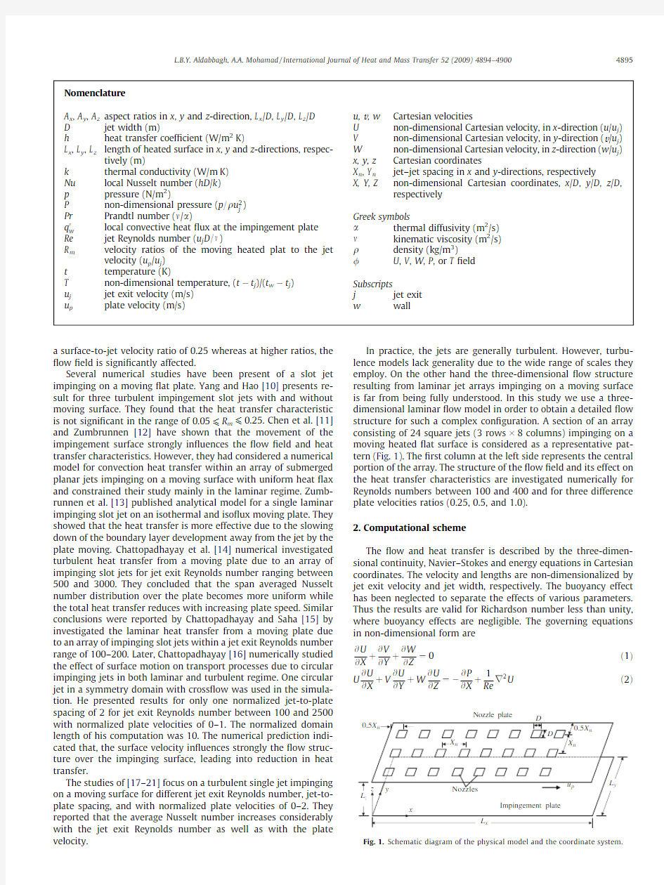
In practice,the jets are generally turbulent.However,turbu-lence models lack generality due to the wide range of scales they employ.On the other hand the three-dimensional ?ow structure resulting from laminar jet arrays impinging on a moving surface is far from being fully understood.In this study we use a three-dimensional laminar ?ow model in order to obtain a detailed ?ow structure for such a complex con?guration.A section of an array consisting of 24square jets (3rows ?8columns)impinging on a moving heated ?at surface is considered as a representative pat-tern (Fig.1).The ?rst column at the left side represents the central portion of the array.The structure of the ?ow ?eld and its effect on the heat transfer characteristics are investigated numerically for Reynolds numbers between 100and 400and for three difference plate velocities ratios (0.25,0.5,and 1.0)https://www.sodocs.net/doc/c29825463.html,putational scheme
The ?ow and heat transfer is described by the three-dimen-sional continuity,Navier–Stokes and energy equations in Cartesian coordinates.The velocity and lengths are non-dimensionalized by jet exit velocity and jet width,respectively.The buoyancy effect has been neglected to separate the effects of various parameters.Thus the results are valid for Richardson number less than unity,where buoyancy effects are negligible.The governing equations in non-dimensional form are
@U @X t@V @Y t@W
@Z ?0e1TU @U @X tV @U @Y tW @U @Z ?à@P @X t1Re
r 2U e2T
Nomenclature A x ,A y ,A z aspect ratios in x ,y and z -direction,L x /D ,L y /D ,L z /D D jet width (m)
h
heat transfer coef?cient (W/m 2K)
L x ,L y ,L z length of heated surface in x ,y and z -directions,respec-tively (m)
k thermal conductivity (W/m K)Nu local Nusselt number (hD /k )p pressure (N/m 2)
P non-dimensional pressure (p =q u 2j )Pr Prandtl number (m /a )
q 00w local convective heat ?ux at the impingement plate Re jet Reynolds number (u j D =m )
R m velocity ratios of the moving heated plat to the jet velocity (u p /u j )t temperature (K)
T non-dimensional temperature,(t àt j )/(t w àt j )u j jet exit velocity (m/s)u p
plate velocity (m/s)
u,v ,w Cartesian velocities
U non-dimensional Cartesian velocity,in x -direction (u /u j )V non-dimensional Cartesian velocity,in y -direction (v /u j )W non-dimensional Cartesian velocity,in z -direction (w /u j )x,y,z Cartesian coordinates
X n ,Y n jet–jet spacing in x and y -directions,respectively
X,Y,Z
non-dimensional Cartesian coordinates,x /D ,y /D ,z /D ,respectively
Greek symbols a thermal diffusivity (m 2/s)m kinematic viscosity (m 2/s)q density (kg/m 3)/U ,V ,W ,P ,or T ?eld Subscripts j jet exit w wall
L.B.Y.Aldabbagh,A.A.Mohamad /International Journal of Heat and Mass Transfer 52(2009)4894–49004895
U @V
@X
tV
@V
@Y
tW
@V
@Z
?à
@P
@Y
t
1
Re
r2Ve3T
U @W
@X
tV
@W
@Y
tW
@W
@Z
?à
@P
@Z
t
1
Re
r2We4T
U @T
@X
tV
@T
@Y
tW
@T
@Z
?
1
Re Pr
r2Te5T
where T is the non-dimensional temperature,(tàt j)/(t wàt j).
2.1.Boundary conditions for velocities
Fig.1shows the schematics of the array of square jets imping-ing on a moving plate.The middle row of jets,which is located at Y=0.5L y,is surrounding by two rows.The additional two rows were added to study the affect of the surrounding jets on the mid row jets.The surface plate is moving in one direction from left to right.As a result,symmetry conditions are used at Y=0and Y=L y.The outlet boundary of the?ow is located far enough down-stream for conditions to be substantially developed.No-slip boundary condition is used for the top solid wall except that the velocity is speci?ed at the exit of the jets,where it is assumed to be uniform and is set to be equal to unity.The bottom solid plate is assumed to move with velocity ratio R m=u p/u j.Accordingly, the following non-dimensional boundary conditions are imposed:
U?@V
@X
?
@W
@X
?0at X?0
@U
@X
?V?W?0at X?A x
V?@U
@Y
?
@W
@Y
?0at Y?0;Y?A y
U?R m;V?W?0at Z?0
U?V?W?0at Z?A z except at nozzle exit;
U?V?0;W?à1at nozzle exit:
2.2.Boundary conditions for temperature
If the?uid exits the domain(at right)the?rst derivative of tem-perature is set to zero and if the?uid?ows from surroundings into the domain then the?uid temperature is set to the surrounding temperature.Symmetry conditions are imposed at the left,front, and rear sides.Adiabatic boundary conditions are used on the top wall,except at the nozzles exit cross section where it was set to be equal to that of ambient.The bottom plate is set to a higher temperature than the ambient.Accordingly,
At X?0@T
@X
?0
At X?A x@T?0for U>0
T?0for U<0
At Y?0;Y?A y@T
@Y
?0
At Z?0T?1
At Z?A z@T
@Z
?0except at nozzle exit
T?0at nozzle exit:
3.Method of solution
The governing equations are discretized by using the?nite vol-ume method in staggered,nonuniform grids.The grids are gener-ated such that denser grid clustering is obtained in the vicinity of the jets in x and y-directions.In the z-direction a sine function dis-tribution is employed,yielding denser grids near the top and near the impingement plate.A grid independence test has been made for Re=200,R m=0,and X n=5in order to determine the effect of the number of grids on the?nal results.The maximum difference between the results obtained by using450?156?54and 338?116?40grids is2.5%for the local Nusselt number.The cor-responding difference between338?116?40and254?90?30 grids is6.7%.Hence,the338?116?40grid system is used in the simulations.The solution domain has L x=47.5D and L y=3X n in x and y-directions,respectively.Special treatment of the advective ?ux is required to accurately capture the velocities in the high gra-dient regions around the jet.QUICK scheme[22]is used to calcu-late the convection of a scalar term,/at a control-volume face. However,this scheme is not bounded and cause oscillations in sharp gradient regions.Many remedies have been proposed.A common approach involves using high-resolution?ux limiters. These limiters are based on composite?ux expressions which in-sure boundedness in regions of sharp gradients and also provide high resolution in monotonic regions.In this work the ULTRA-SHARP?ux limiter[23,24]is used to enforce monotonicity.The ?ux term is applied using a deferred correction technique to reduce the stencil of the discrete equations.In this technique the?ux va-lue estimated by the QUICK scheme is written as the sum of the ?rst-order upwind term plus a correction term,which provides higher accuracy.The?rst-order upwind term is treated implicitly, while the correction term is treated explicitly and added to the source term.The procedure guaranties that the discrete system of equations is diagonally dominant,which is important for itera-tive solvers.In addition the seven diagonal structure of the coef?-cient matrix is preserved,which does not require extra storage.The discretized mass momentum and energy equations are solved in a segregated approach using the standard SIMPLEC[25]algorithm. The momentum equations are solved by using the iterative method SIP of Stone[26],which is extended here to handle three-dimen-sional problems.The pressure-correction equation yields a sym-metric coef?cient matrix,which is solved by using the conjugate gradient method[27].The coef?cient matrix resulting from the en-ergy equation is nonsymmetric and is solved by Bi-CGSTAB[28] iterative method.The coef?cient matrices are preconditioned by SSOR method[29]in order to speed up convergence rate of the iterative solvers.An under relaxation factor of0.5is used for momentum and0.7for energy equations in all calculations.Itera-tions are continued until the second norm of the residuals for all equations are reduced below10à6,where no signi?cant variations are observed at this residual level.In the absence of experimental data under identical conditions the validation of numerical code was performed against the experimental measurements of Spar-row and Wong[30],who used a developed slot-jet?ow impinging on a naphthalene plate.The results are presented in a previous
4896L.B.Y.Aldabbagh,A.A.Mohamad/International Journal of Heat and Mass Transfer52(2009)4894–4900
publication by Aldabbagh and Sezai [31].The agreement between the numerical results and the experimental measurements is in general satisfactory.
4.Results and discussions
Air is used as the working ?uid,having a Prandtl number of 0.71.The analysis is performed for Reynolds numbers between 100and 400,and for the surface velocity ratios,R m =u p /u j ,between 0.25and 1.0.The aspect ratios,A z =L z /D ,was ?xed to be 0.25.Cen-ter-to-center distance values between the jets used are 2D,3D ,4D ,and 5D .The cross section of the nozzles is taken to be square.Fig.2displays the projection of ?ow lines on the mid vertical x –z plane for R m =0,0.5,and 1.0at Re =200and X n =4.The ?ow lines on an x –z plane are obtained from the U and W components of the velocity vectors on that plane.For the case of ?xed heated plate,R m =0,the ?rst column of jets,counted from the symmetry plane on the left,form wall jets upon impingement on the bottom plate which spreads out radially in the absence of any cross?ow effect.After the ?rst column,cross?ow emanating from the upstream jets interferes and de?ects the downstream jets.The jet de?ection increases at downstream side of the array.The for-ward ?owing wall jets,formed by the second column of jets,inter-act with the cross?ow and form ground horseshoe vortices close to the impingement plate,which wraps around the impinging jet like a scarf.After the third column,the jet is bent more under the in?u-ence of increasing cross?ow such that no wall jet can form in the reverse direction of the cross?ow.As a result a ground vortex can-not form in front of the jets and the cross?ow is squeezed on the plate by the jet.For such small jet-to-plate distance used,the cross?ow effect is higher and,as a result,the cross?ow forms a blanket over the bottom plate,preventing jet impingement.For R m >0,the horseshoe formed near the ?rst column and with the same way as in the case of no moving plate.The movement of the plate plays as a cross?ow effect to the ?rst column jets.The velocity ratio of the moving plate increases the cross?ow as a result a ground vortex cannot form in front of the second and third column jets (Fig.2b and c).After the ?rst column,the blanket start form above the bottom plate.The thickness of the blanket increases in a downstream direction due to the increasing of the cross?ow resulting from the upstream jets and the accelerating of the surface movement,as a result increases in jet de?ection.For the range of the velocity ratio of the moving plate used,the ?ow stricture is not affected by increasing R m .Projection of ?ow lines around ?rst four column of jets,on different horizontal planes are shown in Fig.3for Re =200,R m =1.0,and X n =4.For high ele-vations,Z =0.225and 0.125,the jet spreads out radially at the sym-metry plane of the domain.At a distance closer to the bottom plate,Z =0.025,the ground horseshoe vortices formed around the ?rst
5
10
15
20
25
30
35
X
5
6
7
8
Y
three-dimensional plots of the W velocity for Re =200,R m =1.0,and X n =4at the horizontal cross section L.B.Y.Aldabbagh,A.A.Mohamad /International Journal of Heat and Mass Transfer 52(2009)4894–49004897
column.After the?rst column of jets no reverse?ow can form at the collision points of jets for this rather low nozzle-to-plate spac-ing where the strong cross?ow bends the jets in the?ow direction.
A carpet plot of the W component of the velocity is shown in Fig.4 at the horizontal plane Z=0.075for the conditions given in Fig3. The maximum jet velocity occurs at the jet axis for the?rst column of jets.For the next columns,the downward bending of the cross-?ow by the impinging jets augments the vertical velocity and,as a result,the peak of the vertical velocity shifts from the jet axis to-ward the upstream side of the cross?ow.Two additional off-center peaks also form which are offset by about0.5D from the jet axes along y-direction for jets in the third and eighth columns.The for-mation of the off-center velocity peaks along y-direction is similar to that encountered in single and multiple laminar jets with no cross?ow[32–34].
The distribution of the vertical velocity component directly in?uences the heat transfer characteristics as shown in Fig.5, which displays the Nusselt number distribution for the velocity pro?le shown in Fig.4.Heat transfer is expressed in terms of the local Nusselt number as
Nu?hD
k
e6T
where h is the local convection heat transfer coef?cient de?ned as
h?
q00
w
t wàt j
e7T
The local Nusselt number is also equal to the non-dimensional heat ?ux and calculated from Nuex;yT?@T=@Z j
wall
.
In Fig.5the jet stagnation areas are distinguishable clearly as locally high Nusselt number regions with lower heat transfer be-tween jet stagnation zones.At extreme upstream locations in the channel the Nusselt number distribution is about concentric with highest Nusselt number in the center.Downstream,the local heat transfer becomes a superposition of the stagnation?ow and the accumulated channel?ow,which elongates the Nusselt number distribution in the cross?ow direction.The streamwise pro?les of the local Nusselt number along the central line joining the jet cen-ters is depicted in Fig.6corresponding to the velocity pro?les shown in Fig.2.The oscillatory behavior of the Nu pro?les illus-trates the regions of high and low transport directly beneath and between the jets,respectively.Such strong oscillations in the local Nusselt number have been observed previously in jet arrays with cross?ow(Metzger et al.[3],Florschuetz et al.[4],and Garrett and Webb[6]).The amplitude of the periodic oscillations is atten-uated where the peaks diminish and the valleys increase in magni-tude as one proceeds in the downstream direction.A general characteristic common is the increasing shift of the peak value of Nu in the downstream direction,which is associated with the increasing cross?ow magnitude.In addition,the oscillatory behav-ior of the Nu pro?les is not affected by whether the heated plate is ?xed or moving or even by increasing the velocity ratio of the mov-ing plate.The only difference is the heat transfer increase little bit at the left side of the?rst column jets due to the formation of the horseshoe for the case of R m>0.Similar result was observed by Yang and Hao[10]with turbulent slot jets with moving surface for the range of velocity ratio of the moving surface between 0.05and0.25.
The effect of the jet-to-jet spacing,X n,on Nusselt number distri-bution is shown in Fig.7for R m=0.5.The corresponding?ow pro-?les are illustrated through projection of?ow lines on the mid vertical plane in Fig.8.For this small jet-to-plate spacing used, the increasing cross?ow downstream forms a layer blanketing the heated plate through which the jets cannot penetrate.As a re-sult the periodic variations in the Nusselt number pro?le are atten-uated downstream the?ow.The maximum magnitude of the local Nu is shown under the?rst column for X n=2and then a high reduction under the second column.Where as for X n=3the peak of the local Nu for the?rst and second column is same in magni-tude and then high reduction occurs at the third column and shifts downstream at higher X n values.A close examination of the?ow pro?le shows that at locations of high reduction in the local Nu oc-curs,at a place a cross?ow?uid layer blanketing the bottom plate is start form.
Fig.9illustrates the effect of Reynolds number on the pro?les of the local Nusselt number distribution along a streamwise line join-ing jet centers for X n=5and R m=1.For Re>200secondary peaks are formed downstream the jet axes for?rst and second column jets as a result of squeezing the cross?ow on the plate by the downstream jet.The magnitude of the secondary peak increases by increasing Reynolds number and reduced for the same Re till it vanish as one proceeds downstream direction due to increasing cross?ow effect.The increases of the cross?ow are enough to start form the cross?ow?uid layer blanketing the bottom plate under-
4898L.B.Y.Aldabbagh,A.A.Mohamad/International Journal of Heat and Mass Transfer52(2009)4894–4900
neath the fourth column jets.Moreover,the increases of the local Nu at the left of the ?rst column jets is due to the formation of the horseshoe vortices as result of interact the forward wall jets with the cross?ow.
The average Nusselt number values for various surface speed ratio and different jet-to-jet spacing are given in Table 1.The aver-aging is done over the total impingement surface area cooled by the 24jets,which is equal to 24X 2n .For the same surface velocity ratio,R m ,the average Nusselt decreases at larger jet-to-jet spac-ings.This is expected because the jet array with a small jet-to-jet
Table 1
Average Nusselt number for various jet con?gurations.
Nu
R m
0.25 1.0X n =210.43710.58X n =37.287.4X n =4 5.14 5.34X n =5
3.797
4.19
L.B.Y.Aldabbagh,A.A.Mohamad /International Journal of Heat and Mass Transfer 52(2009)4894–49004899
spacing has the smallest surface area cooled per jet,which is equal to X2
n
.Equivalently,the mass?ow rate per unit surface area is high-est for an array system with smaller X n.This means that the surface area cooled by one jet in an array having X n=4is cooled by two jets in an array with X n=2.The average Nusselt number increases with surface velocity ratio,R m.
5.Conclusions
A three-dimensional numerical study has been undertaken to determine the?ow and heat transfer characteristics of impinging laminar array of square jets on a moving surface.The results indi-cate a rather complex?ow?eld with horseshoe vortices formed around the?rst column of jets due to the cross?ow created by the moving surface.The velocity ratio of the moving plate increases the cross?ow as a result a ground vortex cannot form in front of the second and third column jets compared with the case of?x surface. For the range of the velocity ratio of the moving plate used,the ?ow structure in general is not affected by increasing R m.
The streamwise pro?le of the Nusselt number exhibit strong periodic oscillations,spatially.The amplitude of the periodic oscil-lations is attenuated as one proceeds in the downstream direction. In addition,the oscillatory behavior of the Nu pro?les is not af-fected by whether the heated plate is?xed or moving or even by increasing the velocity ratio of the moving plate.
For Re>200secondary peaks are formed downstream the jet axes for?rst and second column jets as a result of squeezing the cross?ow on the plate by the downstream jet.The magnitude of the secondary peak increases by increasing Reynolds number and reduced for the same Re till it vanish as one proceeds downstream direction due to increasing cross?ow effect.
For the same surface velocity ratio,R m,the average Nusselt de-creases at larger jet-to-jet spacings.The average Nusselt number increases with surface velocity ratio,R m.
References
[1]R.Gardon,J.C.Ak?rat,Heat transfer characteristics of impinging two-
dimensional air jets,ASME J.Heat Transfer88(1966)101–108.
[2]D.M.Kercher,W.Tabakoff,Heat transfer by a square array of round air jets
impinging perpendicular to a?at surface including the effect of spent air,J.
Eng.Power92(1970)73–82.
[3]D.E.Metzger,L.W.Florschuetz, D.I.Takeuchi,R.D.Behee,R.A.Berry,Heat
transfer characteristics for inline and staggered arrays of circular jets with cross?ow of spent air,J.Heat Transfer101(1979)526–531.
[4]L.W.Florschuetz,R.A.Berry,D.E.Metzger,Periodic streamwise variations of
heat transfer coef?cients for inline and staggered arrays of circular jets with cross?ow of spent air,ASME J.Heat Transfer102(1980)132–137.
[5]N.T.Obot,T.A.Trabold,Impingement heat transfer within arrays of circular
jets:Part1.Effects of minimum intermediate,and complete cross?ow for small and large spacings,ASME J.Heat Transfer109(1987)872–879.
[6]K.Garrett,B.W.Webb,The effect of drainage con?guration on heat transfer
under an impinging liquid jet array,ASME J.Heat Transfer121(1999)803–810.
[7]K.SubbaRaju,E.U.Schlunder,Heat transfer between an impinging jet and a
continuously moving surface,J.Heat Mass Transfer10(1977)131–136. [8]A.R.H.Van Heiningen,A.S.Mujumdar,W.J.M.Douglas,Flow and heat transfer
characteristics of a turbulent slot jet impinging on a moving wall,in:Abstracts
of the Symposium on Turbulent Shear Flows,Pennsylvania State University, University Park,PA1,1977,pp.3.9–3.15.
[9]J.Senter,C.Solliec,Flow?eld analysis of a turbulent slot air jet impinging on a
moving?at surface,Int.J.Heat Fluid Flow28(2007)708–719.
[10]Y.T.Yang,T.P.Hao,Numerical studies of three turbulent slot jets with and
without moving surface,Acta Mech.136(1999)17–27.
[11]J.Chen,T.Wang,D.A.Zumbrunnen,Numerical analysis of convective heat
transfer from a moving plate cooled by an array of submerged planar jets, Numer.Heat Transfer A26(1994)141–160.
[12]D.A.Zumbrunnen,Convective heat and mass-transfer in the stagnation region
of a laminar planar jet impinging on a moving surface,J.Heat Transfer113 (1991)563–570.
[13]D.A.Zumbrunnen,F.P.Incorpera,R.A.Viskanta,Laminar boundary layer model
of heat transfer due to a nonuniform planer jet impinging on a moving plate,J.
Heat Mass Transfer27(1992)311–319.
[14]H.Chattopadhyay,G.Biswas,N.K.Mitra,Heat transfer from a moving surface
due to impinging slot jets,J.Heat Transfer124(2002)433–440.
[15]H.Chattopadhyay,S.K.Saha,Simulation of laminar slot jets impinging on a
moving surface,J.Heat Transfer124(2002)1049–1055.
[16]H.Chattopadhyay,Effect of surface motion on transport processes due to
circular impinging jets–a numerical study,J.Dry.Technol.24(2006)1347–1351.
[17]H.Chattopadhyay,S.K.Saha,Numerical investigations of heat transfer over a
moving surface due to impinging knife-jets,Numer.Heat Transfer A39(2001) 531–549.
[18]Wu-Shung Fu,Ke-Nan Wang,Wen-Wang Ke,An investigation of a block
moving back and forth on a heat plate under a slot jet,Int.J.Heat Mass Transfer44(2001)2621–2631.
[19]H.Chattopadhyay,S.K.Saha,Turbulent?ow and heat transfer from a slot jet
impinging on a moving plate,Int.J.Heat Fluid Flow24(2003)685–697. [20]Wu-Shung Fu,Ching-Chi Tseng,Chien-Ping Huang,Ke-Nan Wang,An
experiment investigation of a block moving back and forth on a heat plate under a slot jet,Int.J.Heat Mass Transfer50(2007)3224–3233.
[21]M.A.R.Sharif,A.Banerjee,Numerical analysis of heat transfer due to con?ned
slot-jet impinging on a moving plate,Appl.Therm.Eng.29(2009)532–540.
[22]P.Leonard,A stable and accurate convective modelling procedure based on
quadratic upstream interpolation,Comput.Meth.Appl.Mech.Eng.19(1979) 59–98.
[23]B.P.Leonard,S.Mokhtari,Beyond?rst order upwinding:the ULTRA-SHARP
alternative for nonoscillatory steady-state simulation of convection,Int.J.
Numer.Meth.Eng.30(1990)729–766.
[24]B.P.Leonard,J.E.Drummond,Why you should not use‘hybrid’,‘power law’or
related exponential schemes for convective modelling.There are much better alternatives,Int.J.Numer.Meth.Fluids20(1995)421–442.
[25]J.P.Van Doormaal,G.D.Raithby,Enhancements of the SIMPLE method for
predicting incompressible?uid?ows,Numer.Heat Transfer7(1984)147–163.
[26]H.L.Stone,Iterative solution of implicit approximations of multi-dimensional
partial differential equations,SIAM J.Numer.Anal.5(1968)530–558. [27]W.Hackbush,Iterative Solution of Large Sparse Systems of Equations,
Springer,1994.
[28]H.A.V.van der Vorst,BI-CGSTAB:a fast and smoothly converging variant of Bi-
CG for the solution of non-symmetric linear systems,SIAM https://www.sodocs.net/doc/c29825463.html,put.
10(1989)1174–1185.
[29]Y.Saad,Iterative Methods for Sparse Linear Systems,PSW Publ.Co.,Boston,
1996.
[30]E.M.Sparrow,T.C.Wong,Impingement transfer coef?cients due to initially
laminar slot jets,Int.J.Heat Mass Transfer18(1975)597–605.
[31]L.B.Y.Aldabbagh,I.Sezai,Three-dimensional numerical simulation of an array
of impinging laminar square jets with spent?uid removal,Int.J.Therm.Sci.43 (2004)241–247.
[32]I.Sezai,A.A.Mohamad,3-D simulation of laminar rectangular impinging jets,
?ow structure and heat transfer,ASME J.Heat Transfer121(1999)50–56. [33]A.Chatterjee,L.J.Deviprasath,Heat transfer in con?ned laminar axisymmetric
impinging jets at small nozzle-plate distances:the role of upstream vorticity diffusion,Numer.Heat Transfer A39(2001)777–800.
[34]L.B.Y.Aldabbagh,I.Sezai,Numerical simulation of three-dimensional multiple
impinging square jets,Int.J.Heat Fluid Flow23(4)(2002)509–518.
4900L.B.Y.Aldabbagh,A.A.Mohamad/International Journal of Heat and Mass Transfer52(2009)4894–4900