Lighttools机械结构半透明设置


Lighttools中机械结构的透明设置
一、 光学属性的亮度(光泽)和透明度设置
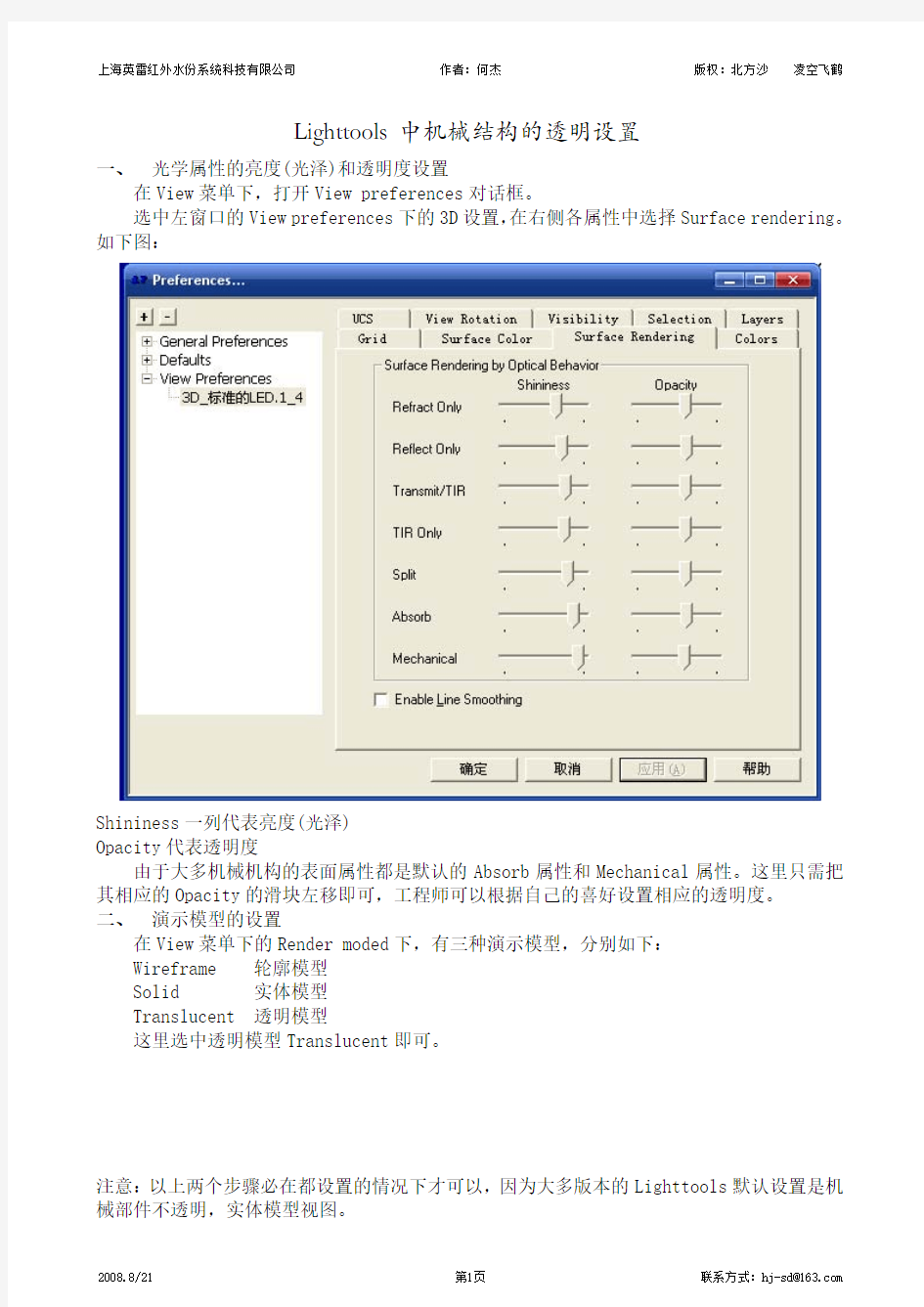
在View菜单下,打开View preferences对话框。
选中左窗口的View preferences下的3D设置,在右侧各属性中选择Surface rendering。如下图:
Shininess一列代表亮度(光泽)
Opacity代表透明度
由于大多机械机构的表面属性都是默认的Absorb属性和Mechanical属性。这里只需把其相应的Opacity的滑块左移即可,工程师可以根据自己的喜好设置相应的透明度。
二、 演示模型的设置
在View菜单下的Render moded下,有三种演示模型,分别如下:
Wireframe 轮廓模型
Solid 实体模型
Translucent 透明模型
这里选中透明模型Translucent即可。
注意:以上两个步骤必在都设置的情况下才可以,因为大多版本的Lighttools默认设置是机械部件不透明,实体模型视图。
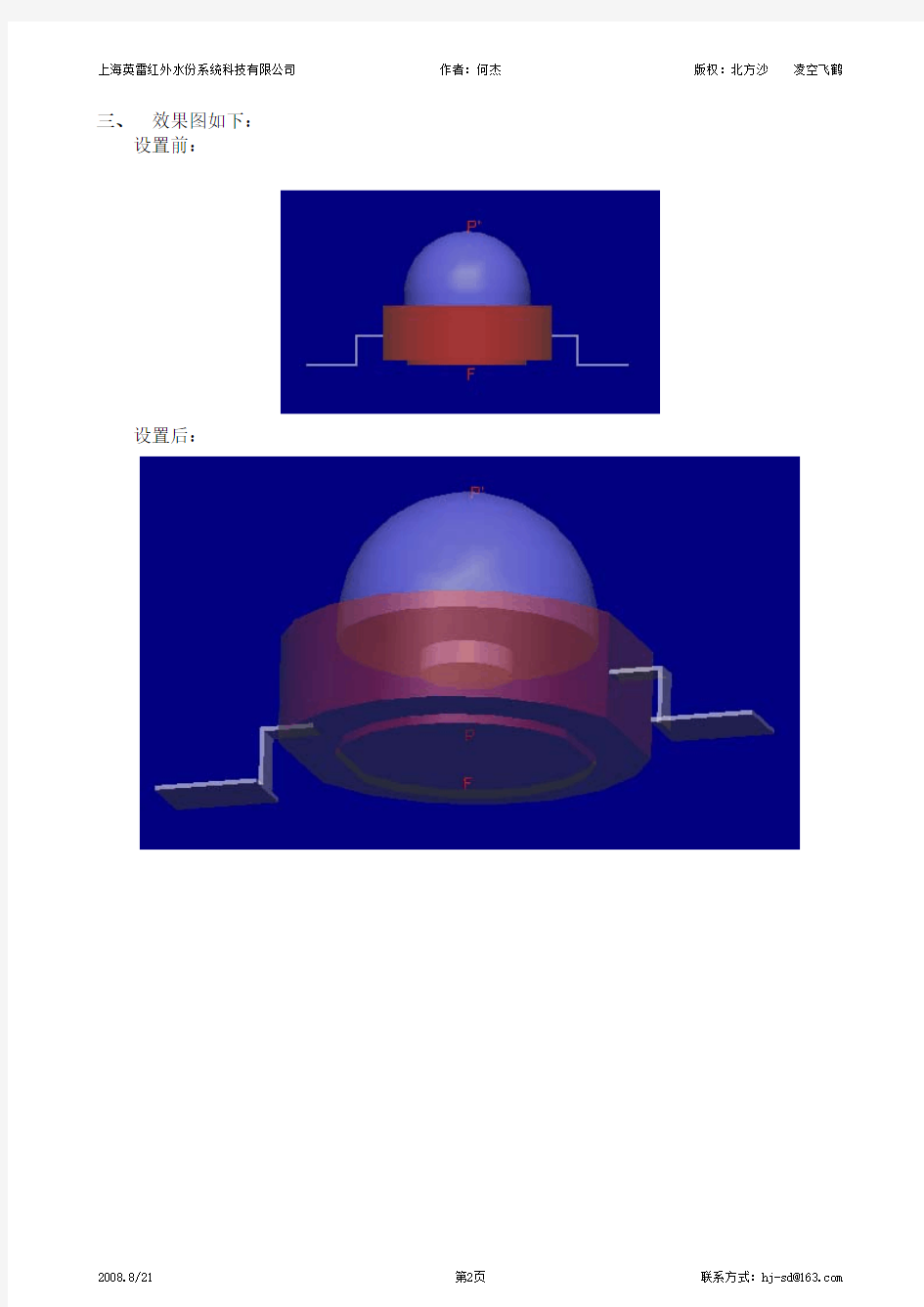
三、 效果图如下: 设置前:
设置后:
LightTools中文教程
照明是光学的主要领域之一,并且正在成为越来越重要,很多公司和它们的产品然而,截至目前为止尚未有一个为照明系统设计和分析的商用软件产品的广泛选择,以及那些已经提供可能都难于使用。正因为如此,对照明系统的设计往往是做通过建立原型和测量它们。 在LightTools照明模块已被写入,以填补这个社会上有需要的光照。它通过计算机进行模拟照明系统准确的定量分析,从而帮助您开发照明产品更迅速和更有信心。 什么是LightTools照明模块? 在LightTools照明模块是一个可选的附加模块向LightTools核心模块。它使用固有的非连续线迹和元素为基础的LightTools建模模拟,以帮助您完成照明系统,包括来源,光学和机械结构。 在LightTools照明模块完全集成在LightTools核心模块,增加新的菜单和命令调色板。因为它是完全集成的,一旦你熟悉了LightTools核心模块,您将很快能够使用后,有关其特殊的特点和要求学习LightTools照明模块。如果您是新的LightTools,我们建议您首先成为熟悉的LightTools核心模块,然后尝试在LightTools照明模块,得到的基本特点和LightTools 的技术,熟悉。 在LightTools照明模块使用非连续的射线追踪。因此,它集成了二维和三维设计视图设计LightTools认为,这两项研究使用非连续的射线追踪。这不是集成了影像路径模块,只使用顺序射线追踪。 照明系统的要素 大部分照明系统具有以下共同特点,所有这些都可以在LightTools照明模块为蓝本。 该系统有一个或更多的光源,通常延长和不均匀,在空间和方位地 用户有必要在分析系统中的几个地点的照度 用户有必要分析远场强度 用户有需要模式不同表面特性,包括菲涅尔损失和散射 用户有一个非连续的光需要跟踪,用蒙特卡罗型概率射线最好跟踪照度计算 · 光源 所有的照明系统至少有一个光源,并可能有几个来源。在LightTools照明模块允许你指定一个来源是无限的。这些来源可以是点源,面三维排放源,排放量或三维来源。 面发射源,可以有空间分布均匀,可以定义和角分布均匀,算法的,或者用户定义的。这些分布可以指定分别为每一个表面的源头体积排放来源是均匀分布的数量或用户定义的,也可以有定义的角分布是均匀或用户。照明光源为模块仿照LightTools照明是光的来源描述更详细研究。 接收机 所有的照明系统至少有一个表面照度在其中的利益(它可能是远场),并可能有几个这样的接收器。在LightTools照明模块允许你指定一个无限数量的接收器。光照接收机作为模块仿照LightTools照明是接收机更详细描述 表面性质 在LightTools核心模块,您可以指定每个任何物体表面三维固体表面性质分开。这些属性包括屈光模式(折射,公路货运,反映等)以及表面处理(衍射,散射等)。光学对象,这些属性可以指定单独的表面上不同的区域 蒙特卡罗光线追踪 在LightTools照明模块照明分析是基于蒙特卡罗光线跟踪。该方法从随机挑选的痕迹点的射线所需的数字(可以是几千甚至几百万的射线)对地表,或在数量,来源(或来源)和空间将随机选择angles。作者的出发点和线方向选择是基于描述光源的发光特性的概率函
Light Tools软件介绍
LightTools 简介 LightTools 是一个全新的具有光学精度的交互式三维实体建模软件体系,提供最现代化的手段直接描述光学系统中的光源、透镜、反射镜、分束器、衍射光学元件、棱镜、扫描转鼓、机械结构以及光路。由于LightTools 把光学和机械元件集合在统一的体系下处理,并配有“放置”光源、发射光线的非顺序面光线追迹的强大功能,使它在系统初步设计、复杂系统设计规划、光机一体设计、杂光分析、照明系统设计分析、单位各部门间学术交流和数据交换、课题论证或产品推广等各环节中均可发挥重要的作用,成为人们理想的工具。 LightTools 简介 美国Optical Research Associates (ORA?) 公司以研制国际领先的CODE V? 光学工程软件而著称于世。1995年,该公司根据用户需求和计算机技术的发展,隆重推出最新产品—光学系统建模软件LightTools,马上得到各国用户的欢迎和好评,并获得国际大奖。1997年,ORA 又研制成功与LightTools 主体程序配套使用的Illumination 模块,圆满地解决了照明系统的计算机辅助设计问题。 其中的主要功能简单介绍如下: 系统建模 提供多种展现系统光机模型的方式和人机交互的手段。使用者可直接在系统的二维、三维线框图或三维实体模型图上进行各种操作。方便易用的图形交互式建模和修改功能包括元件或元件组的放置、移动、旋转、复制和缩放。操作时既可用鼠标以实时观察修改造成的效果,也可用键盘以输入准确的数据。透镜、反射镜和棱镜等光学元件及各种机械件可以极快地以图形方式“画入”系统。系统数据可以用表格和元件详情对话框的形式列出和修改。所有上述各种输入方式同时并存,可交替使用。 光机一体化设计 光学和机械元件的形状的描述是通过对软件提供的一组尺寸可变的基本实体模型做布尔运算(与、或、异等等)实现的。这些光学或机械部件的形状虽然可能非常复杂,但均可以在软件中得到精确的展现和描绘,并以光学精度进行光线追迹。遮光罩、镜筒和产品结构的设计均将大大得益于这种光机一体的考虑方法和非顺序光线追迹提供的大量信息。 复杂光路设置 在光学设计中,LightTools 可以和ORA 公司研制的CODE V 软件配合使用。特别是在多光路或折迭光路系统、带有棱镜或复杂曲面的系统的光路设置和视觉建模型验证中,LightTools 将发挥重要作用。有了LightTools,设计人员完全可以摒弃过去为了简化问题而采用的一些传统技巧,如符号规则、用多通道定义模拟变焦功能、把反射镜和棱镜展开成平板、略去非光学面和机械结构的影响、人为简化光瞳形状,等等。
lighttools背光源设计实例
Introduction Backlights are used for compact, portable, electronic devices with flat panel Liquid Crystal Displays (LCDs) that require illumination from behind. Applications include devices as small as hand-held palm pilots and as large as big-screen TVs. Goals for backlight design include low power consumption, large area with small thickness, high brightness, uniform luminance, and controlled viewing angle, either wide or narrow. To achieve these challenging design goals with a cost effective and timely solution, it is necessary to use computer-aided optical design tools to expedite the design. This paper describes fea-tures in ORA’s LightTools? illumi-nation design and analysis software that enable the development of state-of-the-art backlight designs. Optical Design and Analysis Tools for Backlights Illumination or lighting systems take light from one or more sources and transform it in some way to produce a desired light distribution over an area or solid angle. Illumination design software must be able to model the geometric and optical properties of different types of light sources and transforming elements, and it must also be able to evaluate the paths of light using optical ray tracing through the model to calcu-late the final light distribution.The light distributions are calculated using Monte Carlo simulations to calculate illuminance, luminance, or luminous intensity over the desired areas and/or angles. Rays are started from random locations and direc- tions from the source(s), traced through the optical system, and col- lected on receivers. Illuminance can be calculated for rays collected on surface receivers and intensity for rays collected on far field receivers. By defining a luminance meter for surface receivers, the spatial or angular variation of luminance can be calculated from that surface. In some cases, it may be important to analyze the chromaticity of a dis- play. The spectral energy distribu- tion of the sources (such as LEDs) can be specified. The output of CIE coordinates, together with corre- lated color temperature (CCT), quantifies the colorimetric behavior of the display. An RGB photorealis- tic rendering of the display output can also be generated. All of these analyses are available in LightTools. Aspects of backlight displays make particular demands on illumination analysis software. As will be dis- cussed, the means by which light is extracted from a backlight relies on either dense patterns of paint dots or patterned microstructures. Model- ing microstructure arrays in particu- lar can result in extremely large model sizes if created explicitly as a CAD model. LightTools provides the capability to define arrays of 3D textures that ray trace and render accurately but are not explicitly con- structed as part of the geometric model, thereby resulting in much smaller model sizes and much faster ray tracing. A second aspect of backlight analy- sis involves ray splitting and scatter- ing from the surfaces of the light guide. Because Monte Carlo simu- lations are used to analyze the illu- mination performance, a potentially large number of rays must be traced to get sufficient accuracy for com- parison of designs. It is most effec- tive to trace rays that carry most of the flux. This can be achieved by using probabilistic ray splitting to trace the paths with the most flux, and allowing use of aim areas or solid angles for scattering surfaces to direct scattered light in “important” directions (i.e., toward the display observer). What is a Backlight? A typical backlight consists of a light source, such as a Cold Cathode Fluorescent (CCFL) or Light Emit- ting Diodes (LEDs), and a rectangu- lar light guide, which is also referred to as a light pipe. Other elements than can be used include a diffuser, which enhances display uniformity, and a brightness enhancement film (BEF), which enhances display brightness. The light source is usually located at one edge of the light guide to mini- mize the thickness of the display. Edge lighting typically uses total internal reflection (TIR) to propa- gate light along the length of the dis-Optical Design Tools for Backlight Displays
[说明]lighttools中文说明
[说明]lighttools中文说明 第一章介绍 翻译:郑一狼 照明作为光学领域中的一个重要部分,对于很多公司和它们的产品来说正变得越来越重要。可是,直到现在对于照明系统设计和分析来说还没有可供广泛选择的专业软件,能够应用于照明系统的软件也很难使用。正因为如此,目前照明系统的设计通常是建立系统的模型然后测试此模型。 LightTools的照明模块是为了满足照明行业的需要而编写的。它通过计算机建模对照明系统进行精确的定量分析,从而帮助你更加快速有效的开发照明产品。 一.什么是LightTools照明模块, LightTools照明模块是LightTools核心模块的可选的扩展模块。它使用非序列性光线追迹并且基于元件进行建模,帮助你模拟完整的光学系统,包括系统的光源、光学元件和机械结构。 LightTools照明模块完全与LightTools核心模块相结合,并且添加了新的菜单和命令。因为两个模块是相互结合的,一旦你熟悉了LightTools核心模块,那么在你了解了LightTools照明模块的一些特性后,将很快能够使用LightTools照明模块。如果你是使用LightTools的新手,那么我们推荐你在学习LightTools照明模块之前先熟悉LightTools核心模块,以此来熟悉LightTools的基本特性和操作。 LightTools照明模块使用非序列性光线追迹,这点和2D及3D设计视图是一致的,但是和Imaging Path模块不一样,Imaging Path模块只使用序列性光线追迹。 二(照明系统基础
大部分照明系统拥有以下这些特性,所有以下这些特性都可以在LightTools 中被模拟。 , 系统有一个或更多的照明光源,通常成一定角度并且不 均匀地分布在三维空间中。 , 我们需要在系统的若干位置分析照度。 , 我们需要分析远场的发光强度。 , 我么需要创建不同的曲面属性,包括菲涅尔损失和散射 特性。 , 我们需要进行非序列性光线追迹,对于照明计算可能更 适宜使用蒙特卡洛类型随机光线追迹。 1) 光源 任何一种照明系统至少要有一个光源,或者有几个光源。 LightTools照明模块允许你指定无限多个光源。这些光源可以是点光源、三维面光源或者三维立体光源。 面光源可以有一个统一的或者用户定义的空间分布,并且可以有统一的、朗伯的(Lambertian)、或者用户定义的角度分布。可以为光源的每个面单独指定这些分布。 立体光源可以有一个统一的或者自定义的空间分布,并且能够有一个统一的或者自定义的角度的空间分布。 使用LightTools照明模块建立光源模型的细节请参考Light Soruces部分。 2) 接收器 所有的照明系统至少有一个面上的照度很重要(它可能是远场位置的面),并且可能有相应的若干个这样的接收器。
lighttools中文说明
第一章介绍 翻译:郑一狼 照明作为光学领域中的一个重要部分,对于很多公司和它们的产品来说正变得越来越重要。可是,直到现在对于照明系统设计和分析来说还没有可供广泛选择的专业软件,能够应用于照明系统的软件也很难使用。正因为如此,目前照明系统的设计通常是建立系统的模型然后测试此模型。 Li gh tT oo ls的照明模块是为了满足照明行业的需要而编写的。它通过计算机建模对照明系统进行精确的定量分析,从而帮助你更加快速有效的开发照明产品。 一.什么是L i gh t To o l s照明模块? Li gh tT oo ls照明模块是L i gh tT oo ls核心模块的可选的扩展模块。它使用非序列性光线追迹并且基于元件进行建模,帮助你模拟完整的光学系统,包括系统的光源、光学元件和机械结构。 Li gh tT oo ls照明模块完全与Li gh t To ols核心模块相结合,并且添加了新的菜单和命令。因为两个模块是相互结合的,一旦你熟悉了Li gh tT oo l s核心模块,那么在你了解了Li gh t To ol s照明模块的一些特性后,将很快能够使用L ig ht To ol s照明模块。如果你是使用L i g h t T o o l s的新手,那么我们推荐你在学习L i gh tT oo l s照明模块之前先熟悉Li g ht To ol s核心模块,以此来熟悉Li gh tT oo l s的基本特性和操作。 Li gh tT oo ls照明模块使用非序列性光线追迹,这点和2D及3D设计视图是一致的,但是和I ma gi ng Pa th模块不一样,I m ag in g P a th模块只使用序列性光线追迹。 二.照明系统基础 大部分照明系统拥有以下这些特性,所有以下这些特性都可以在Li gh tT oo l s中被模拟。 ●系统有一个或更多的照明光源,通常成一定角度并且不 均匀地分布在三维空间中。 ●我们需要在系统的若干位置分析照度。 ●我们需要分析远场的发光强度。 ●我么需要创建不同的曲面属性,包括菲涅尔损失和散射 特性。 ●我们需要进行非序列性光线追迹,对于照明计算可能更 适宜使用蒙特卡洛类型随机光线追迹。 1)光源 任何一种照明系统至少要有一个光源,或者有几个光源。L i gh tT oo ls照明模块允许你指定无限多个光源。这些光源可以
相关文档
- lighttools光学模拟软件使用手册
- lighttools 基本操作(第1-2节课)
- Lighttools 图标指令明细表
- lighttools光学模拟教程
- lighttools背光源设计实例
- lighttools基本操作ppt课件
- Lighttools教学材料2
- lighttools基本操作简讲
- Light Tools软件介绍
- lighttools基本操作(课)精讲
- Lighttools基础教程 PPT课件
- lighttools中文说明
- Lighttools基础教程
- LightTools-照明设计解析软件
- LightTools8.2仿真应用全教程
- lighttools光学模拟教程
- Lighttools 图标指令明细表
- LightTools 8.2.0仿真应用教程
- [说明]lighttools中文说明
- lighttools基本操作(课)精讲专题培训课件
