Visual servoing by partitioning degrees of freedom
Visual Servoing by Partitioning Degrees of Freedom Paul Y.Oh,Member,IEEE,and Peter K.Allen,Member,IEEE
Abstract—There are many design factors and choices when mounting a vision system for robot control.Such factors may include the kinematic and dynamic characteristics in the robot’s degrees of freedom(DOF),which determine at what velocities and fields-of-view a camera can achieve.Another factor is that additional motion components(such as pan-tilt units)are often mounted on a robot and introduce synchronization problems. When a task does not require visually servoing every robot DOF, the designer must choose which ones to servo.Questions then arise as to what roles,if any,do the remaining DOF play in the task.Without an analytical framework,the designer resorts to intuition and try-and-see implementations.This paper presents a frequency-based framework that identifies the parameters that factor into tracking.This framework gives design insight which was then used to synthesize a control law that exploits the kinematic and dynamic attributes of each DOF.The resulting multi-input multi-output control law,which we call partitioning, defines an underlying joint-coupling to servo camera motions.The net effect is that by employing both visual and kinematic feedback loops,a robot can quickly position and orient a camera in a large assembly workcell.Real-time experiments tracking people and robot hands are presented using a5-DOF hybrid(3-DOF Cartesian gantry plus2-DOF pan-tilt unit)robot.
Index Terms—Coupled systems,gantry,hybrid robot,parti-tioning,robot control,tracking,visual servoing.
I.I NTRODUCTION
A ROBOT is physically characterized by the kinematic and
dynamic attributes of its degrees of freedom(DOF).The number,range limits,and time responses of the DOF define the robot’s performance.A vision system is often mounted on a robot with image data servoing the DOF into desired camera poses.In designing a control law to govern these robot-mounted camera motions,one must choose which robot DOF to invoke and determine if they are well suited for the designated visual control task.For example,tracking tasks require choosing robot DOF with fast response times so that the camera can be quickly centered over the moving target.Workspace monitoring tasks,however,may demand wide fields-of-view,and thus one chooses DOF that permit a larger range of motion(albeit possibly slower)for camera maneuvering.
In addition to the task,other factors confound the choice of which DOF to invoke.Oftentimes,a robot is retrofitted with
Manuscript received January7,2000;revised August28,2000and De-cember28,2000.This paper was recommended for publication by Associate Editor Y.Xu and Editor V.Lumelsky upon evaluation of the reviewers’comments.This work was supported in part by an ONR/DARPA MURI Award ONR N00014-95-1-0601and the National Science Foundation under Grant CDA-96-25374.This paper was presented in part at the International Conference on Robotics and Automation,San Francisco,CA,2000.
P.Y.Oh is with the Mechanical Engineering and Mechanics Department at Drexel University.
P.K.Allen is with Columbia University,New York,NY10027USA. Publisher Item Identifier S1042-296X(01)03158-5.additional motion components such as a configurable gripper or a motorized pan-tilt unit(PTU)that holds the camera.This results in a hybrid robot with extra layers of motion control. These components introduce additional servo update rates to the robot’s underlying trajectory generator.The net result is dis-parate timing loops and this requires proper gain tuning to co-ordinate all robot DOF and avoid a misconfigured camera pose.
A robot with many DOF(possibly redundant)can also present multiple choices for visual-servoing implementation.For ex-ample,in centering the camera’s image plane over a moving target,only two DOF,like pan and tilt,may be required.The questions that arise are as follows:which two to choose and what roles,if any,do“left-over”DOF play.
Pose regulation is ubiquitously discussed in the visual ser-voing literature and implemented on6-DOF robots to track geo-metrically simple targets like blocks,cylinders,and spheres[8], [9],[13],[17],[3].It is a specific case where no design choices, aside from image feature selection,resulting image Jacobian, and gain tuning,are really necessary since every DOF is visu-ally servoed.Its design synthesis and implementation are well known[11].Pose regulation forces the end-effector mounted camera to mimic target motions.One only needs to define the image and manipulator Jacobians to achieve this task in joint space.The caveat,however,is that all the robot’s DOF must have sufficient bandwidth to keep the target’s fiducials in view. The DOF with the slowest time response will limit performance. Corke discusses how lag errors result from ignoring robot dy-namics in the control law and prescribes compensator designs [5].Kalman filtering[1],[18]is an alternative solution,but re-quires a priori knowledge of target trajectory which is not al-ways available.
In the big picture,when visual servoing of all the robot’s DOF is not required,like camera centering over a moving target,a more general problem arises.The combination of task,robot DOF attributes,motion component update rates,and multiple DOF choices compound the decision of which DOF to invoke through visual servoing.Tracking more geometrically complex targets,without a priori knowledge of trajectories,in unstruc-tured environments add to this problem.One must then resort to trial-and-error implementations and perhaps ad hoc gain tuning of the control laws.
This paper presents a design methodology under an analyt-ical framework.Frequency-based domain techniques are used to decide which DOF should be visually servoed and root-locus is used for gain tuning.This analysis is then used to develop a novel multi-input multi-output control scheme we call parti-tioning[14].The scheme defines an underlying joint-coupling among the various DOF using both image and kinematic joint data.Joint-coupling and kinematic data are introduced to actuate DOF that are not visually servoed but still serve in the vision
1042–296X/01$10.00?2001IEEE
(a)(b)
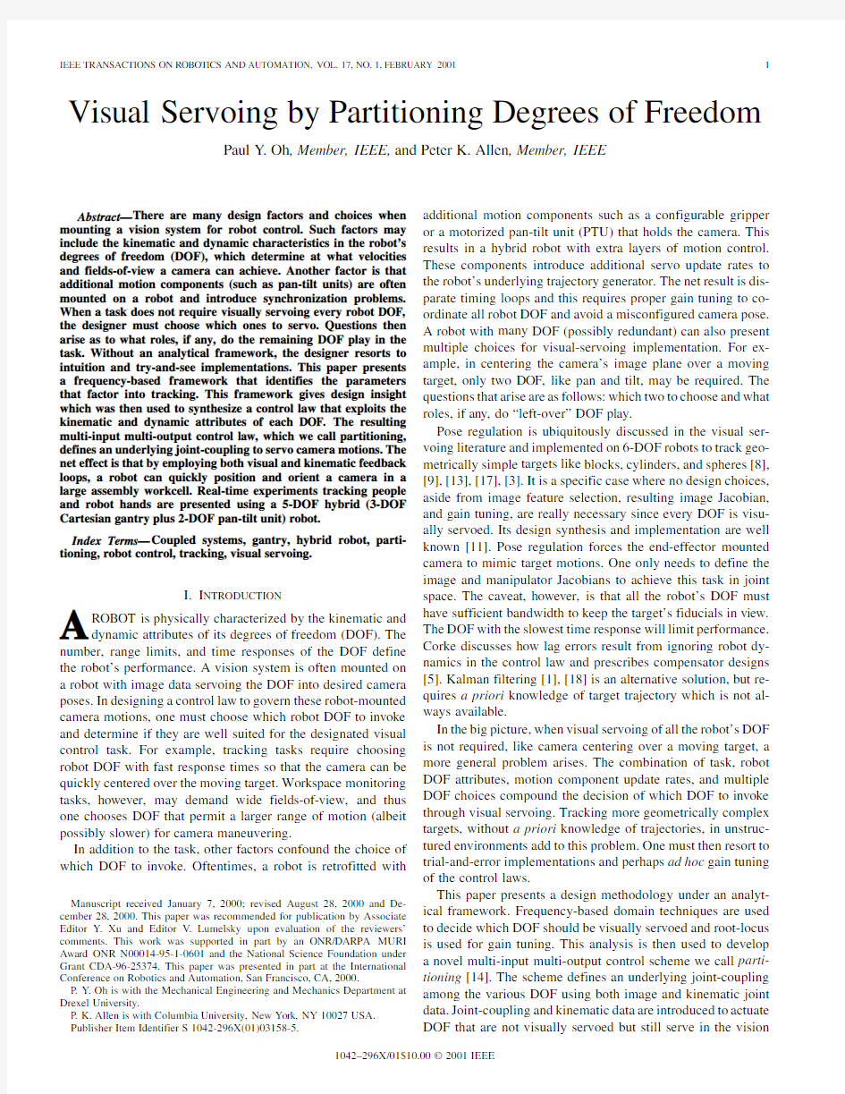
Fig.1.(a)The workcell contains two Puma robots.The gantry and PTU can position and orient the camera anywhere in the workcell.(b)The desired vision system would automatically track objects like grippers,tools,and workpieces the Pumas manipulate.
task.The paper presents its implementation on an eye-in-hand 5-DOF hybrid robot.This robot is a 2-DOF PTU mounted on a 3-DOF Cartesian gantry that can track geometrically complex targets like tools,workpieces and grippers,which have nonde-terministic motion trajectories,over a large
3.6
1
m
m
10m /s t e p r e s o l u t i o n s w i t h m a x i m u m v e l o c i -t i e s o f 0.7a n d 0.5m /s ,r e s p e c t i v e l y .M o t o r 3h a s a 3.75150
/s m a x i m u m v e l o c i t y )a n d t i l t (
t o /s m a x i m u m v e l o c i t y )a n g l e s a n d v e l o c i
m o n i t o r e d a n d c h a n g e d o n -t h e -f l y .T h e n e t e f f h y b r i d e y e -i n -h a n d r o b o t w i t h t w o s e p a r a t e m o a n d w i t h d i f f e r e n t s e r v o u p d a t e r a t e s .
I m a g e s a r e a c q u i r e d w i t h a n o f f -t h e -s h e l f c d e v i c e (C C D )c a m e r a a n d d i g i t i z e d b y a S p a r c f r a m e g r a b b e r a n d X -V i s i o n [10]w a s u s e d f o r
c e s s i n g .T
h e S p a r c i s t h e h o s t c o m p u t e r w h i c h d a t a (a c q u i s i t
i o n a n d p r o c e s s i n g )a n d i s s u e s g a n t r y a n d P T U m o t i o n c o m m a n d s v i a s e r i a l c o m
OH AND ALLEN:VISUAL SERVOING BY PARTITIONING DEGREES OF FREEDOM
3
Fig.3.Robot and hardware
communications.
Fig.4.The camera-to-hand pose is to be regulated.For co-planar fiducial marks(black squares)were taped onto the hand and tracked with four SSDs returning(ui;ui),i=11114pixel locations.
The Sparc-to-PC and Sparc-to-PTU communicates at38400 and9600baud,respectively.The gantry’s PC motion board updates stepper pulses every30ms and low-level interrupt programming was used to minimize serial latency to6ms. The PTU however has a large latency(0.12s)due to Unix context switching.The PTU uses proprietary firmware and has no provisions to handle low-level handshaking.To main-tain fast image handling,Unix’s multitasking capabilities were exploited by generating two processes connected by an interprocess pipe.The first,a vision-handling process grabs and processes image data continuously.Its loop rate depends on the amount of image processing computation required.It oversamples by repeating computations on image data stored in video memory until a new frame of image data is acquired. This oversampling results in loop rates faster than30Hz.The second,a main process,requests pixel data,computes,and then issues PTU and gantry commands.The net effect is an integrated robot-vision system that could acquire real-time image data and move the camera in five DOF(see Fig.3).
In using this robot for visually-servoed tracking,we first implemented a pose regulation scheme,Fig.4,to perform the classic block/plane following experiment[8],[9],[13],[17], [3].Given known side-lengths,the plane’s pose is extracted from the image positions of four co-planar fiducials painted on the target.In our implementation,we used four
40
4IEEE TRANSACTIONS ON ROBOTICS AND AUTOMATION,VOL.17,NO.1,FEBRUARY
2001
Fig.5.Block diagram for pan-only design.
This gives quantitative measures of each DOF’s tracking per-formance.Bandwidth,phase characteristics,and root locus gain tuning are then used to choose a suitable DOF pair.
III.A NALYTICAL F RAMEWORK
Our tracking task is the visually-servoed centering of the camera’s image plane over a moving target.The analytical framework used to measure task performance is frequency based.The target is oscillated and the frequency response (bandwidth and phase)of the visually-servoed DOF is mea-sured.This task only requires measuring the center of gravity of the target’s image centroid.The resulting
horizontal
pixel position pair is compared to the pixel location
of the image plane center and camera motions are invoked to minimize the difference.Typically,the invoked motions are velocity commands,and tracking in this manner is cited in the visual-servoing literature as piloting [4]or steering [5].
These two references also report frequency response results of visually-servoed DOF.The former used a target placed on a turntable (for pan-tilt response)and the later used a pair of alter-nating LEDs.Beyond reporting frequency response results and gain tuning,we analyze frequency responses for design insight.Bandwidth and phase quantitatively identify the advantages and disadvantages of visually servoing a DOF.Our end goal is to then design a controller that combines these advantages;the re-sult would exploit each DOF’s kinematic and dynamic attributes to increase tracking performance.
Our analytical framework,to meet this end goal,begins by identifying the design parameters that affect tracking perfor-mance.Such parameters include communication latencies and gains.We thus mathematically model,in Section III-A,two vi-sually servoed,input–output,tracking systems.The first invokes pan only and the second invokes a single gantry DOF
(
,which is limited by communication latency.
The PTU and gantry have different latencies.These factors show up as parameters in the following mathematical models.1)Pan-Only Tracking Model:The transfer function model for visually servoing the pan DOF only can be derived using the discrete-time block diagram (Fig.5).It shows both sample
instants
-axis.
can
be alternatively expressed as a bearing
angle
and
is the angle the target makes with
respect to the lens center.A pin-hole camera model
yields
(2)
OH AND ALLEN:VISUAL SERVOING BY PARTITIONING DEGREES OF FREEDOM5
Fig.6.Relevant notation used for linearization.
where
is the lens focal length in pixels.
The two previous equations combine to form
and in the camera’s
image plane.
Fig.5shows these two relationships as block elements before
and after the adder and yields an image position
is a set point image location.Before tracking
begins,the camera pose is initialized so that its image plane is
centered over the target.Without loss of generality,let
(t)=K[kT].
6IEEE TRANSACTIONS ON ROBOTICS AND AUTOMATION,VOL.17,NO.1,FEBRUARY2001
Fig.7.Gantry-only block diagram.
since no bearing angle relationship is necessary.
0.3Hz(1.9rad/s)with a phase angle of
(
yields a dominant pole at
on the real then for
Hz(1.048rad/s)and phase angle of
and
,were selected in light of known
stepper motor start/stop frequency ranges and at these values
there is no stall.Root locus plots(not shown),derived from the
transfer function models,can be used to tune performance(rise
time and overshoot behaviors).
1)Design Insights:Tracking necessitates keeping the target
in the camera’s field-of-view and large bandwidth DOF should
be employed to afford fast camera servoing.As such,the fre-
quency responses reveal that PTU DOF are more suited for vi-
sual servoing than gantry DOF.
To reiterate our end goal,we want to design a controller that
combines the advantages that each DOF offers by exploiting
OH AND ALLEN:VISUAL SERVOING BY PARTITIONING DEGREES OF FREEDOM
7
(a)
(b)
(c)(d)
Fig.9.Bode magnitude and phase plots for (a),(b)pan-only and (c),(d)gantry-only tracking.Both experimental (dots)and modeled (solid)plots are shown.
its kinematic and dynamic attributes.The modeling and the dynamic attributes of visually-servoing camera rotations and camera translations reveal design insights.First,pan-only tracking performance depends on small camera-to-target bearing angles,but its bandwidth affords fast camera motions.Second,although gantry-only tracking is sluggish as indicated by its smaller bandwidth,there is very little attenuation.
These insights suggest that better tracking,through camera rotations,can be achieved by cutting the bearing angle between the camera and target.This requires translating the camera.One way to achieve both camera rotation and translation is to define an underlying joint-coupling between the rotational and trans-lational DOF in a control law.Its synthesis would exploit the PTU’s large bandwidth by visual servoing rotational DOF (pan and tilt).This keeps the camera’s image plane centered over the target.The pan and tilt angles are then used to kinematically servo the gantry to exploit its ability to translate and cut down the camera-target bearing angle.The net effect is a multi-input multi-output control architecture,we call partitioning [14],[15],that improves tracking performance.
IV .P ARTITIONING
A paradigm one notices in the visual-servoing literature are control laws that exclusively use image data to command camera motions.Kinematic data,like joint encoder positions are sometimes added in feedback or feedforward loops in dynamic image-based look and move structures [11]to achieve faster response.This hints that joint and image data combi-nations can afford novel controllers for visual servoing.For example,in a unique approach [2]modeled visual compliance after well-understood force compliance techniques.
One control strategy,when multiple sensors (like camera and joint encoders)provide possible command inputs,is to define an underlying joint-coupling in the servoing law.Observing the be-haviors people display when visually tracking also suggests that we use an underlying joint-coupling.One behavior is that the eyes and neck typically pan in the same direction when tracking.Another is that the eyes also lead (i.e.,start panning before)the neck;as the eyes reach their kinematic joint limits,neck pan commences.A possible explanation for such behaviors is we
8IEEE TRANSACTIONS ON ROBOTICS AND AUTOMATION,VOL.17,NO.1,FEBRUARY
2001
Fig.10.Coupled pan-gantry block diagram.Notice the similarity with Figs.5and 7.
use both image and kinematic data when coordinating our DOF.Visually servoing DOF with fast response times (like the eyes)physically serve as lead compensators (add phase)for joints that are slower to react.Skeet shooting is a good physical example of lead compensation.Often a marksman will add phase by aiming ahead of the target to compensate for relative motion dynamics and reaction time (latencies).
The explanation for the observed human tracking behaviors is conjecture but joint-coupling can be implemented in the con-trol law and is illustrated in Section IV-A.Step response exper-iments tracking a robot hand are also featured.Bode plots and peak-to-peak pixel error measurements (that give a clearer rep-resentation of phase lags)are given in Section IV-B.
A.Coupled Pan-Gantry Tracking Model
A 2-DOF joint-coupled system is realized as a block diagram in Fig.10and is structurally similar to a combination of Figs.5and 7.The net camera motion we wish to achieve is a coupled one;pan always centers the camera over the target and gantry translation is achieved through a joint-coupling,described as follows.
The block diagram has two distinct feedback loops:the first embeds a linearized pan-only steering design.Here,camera pan
velocity
(superscript
in
and
is the
camera’s radius of rotation,
and
40SSD was used to acquire the center of
gravity pixel coordinates of the robot hand’s image centroid (left-most).The coupled pan-gantry step response was achieved by first translating the robot hand by 0.1m (middle)then letting the pan and gantry DOF servo the camera (right-most).The gridded background highlights the resulting pan and gantry motions.
The pan angles and the gantry positions were recorded during the above experiment (dashed lines)and are plotted in Fig.12.The results correspond closely to computer simulations (solid lines)using the transfer functions (10)and (11).
Gains
and were selected using root locus plots (Fig.13)de-rived from these transfer functions and yield closed-loop pole positions that correspond to a damping ratio
of
OH AND ALLEN:VISUAL SERVOING BY PARTITIONING DEGREES OF FREEDOM
9
Fig.11.Three image stills taken from a videotape of the coupled pan-gantry system step
response.
Fig.12.Coupled pan-gantry step response.Experimental(dash)and simulations(solid)shown.
cluding
the
to yield a good compromise
in both stability and performance.
The(target position)step input causes a rapid camera pan
acceleration and simultaneously invokes gantry translation due
to
the
(with)coupling.This gantry action conse-
quently brings the camera closer to the target and thereby cuts
the camera-to-target bearing angle,
thus decreases.The net
effect is that the final camera’s image plane is centered over and
parallel to the target.
B.Frequency Response and Peak-to-Peak Pixel Errors
The frequency domain offers a clearer explanation of
joint-coupling effects.As mentioned previously,the visu-
ally-servoed pan DOF physically acts as a lead compensator
for the kinematically servoed gantry https://www.sodocs.net/doc/e11923569.html,pensators can
be mathematically designed using feedforward or feedback
techniques[6]to place or cancel system poles and zeros
and improve lag.Beyond these mathematical abstractions,
however,compensation can also be physically achieved with
joint-coupled partitioning as seen in the following sinusoidal
input response.
In one experiment,Fig.14,the robot hand oscillated hori-
zontally at0.1Hz
(period over
time[m](solid thick line).The pan and
gantry joint responses were recorded(dashed lines).Gantry lag
is quite obvious with its peak following the input peak.The pan
leads the gantry as evidenced by the pan peak coming before
the gantry peak.Simulations using(10)and(11)are also shown
(solid lines)and correspond closely to experimental results.
1)Partitioned Joint-Coupling Bode Plots:The pan DOF
acts like a lead compensator.This can be seen from
the
(a)
(b)
Fig.13.(a)Fixed root locus with
z
00:042z+
0:00252)=(0:25z+0:25z=1:0and varying
00:5z00:042z).
Closed-loop pole positions(boxes)lie on damping ratio line =0:95
.
Fig.14.Coupled pan-gantry response to a0.1-Hz,0.1-m amplitude sinusoidal
target translation x
10IEEE TRANSACTIONS ON ROBOTICS AND AUTOMATION,VOL.17,NO.1,FEBRUARY2001
(a)(b)
(c)(d)
Fig.15.Bode plots of coupled pan-gantry:(a),(b)pan magnitude and phase,(c),(d)gantry magnitude and phase for =1:0.Both Matlab-generated (solid)and experimental(dot)results are shown.The pan’s magnitude peaks at0.189Hz with a12.95dB gain and0
phase angle.
Bode phase and magnitude plots which were obtained in
the same manner as in Section III-B.Both
55.88
40.652.8
OH AND ALLEN:VISUAL SERVOING BY PARTITIONING DEGREES OF FREEDOM
11
(a)
(b)
Fig.16.
(a)Pixel errors for both gantry-only (
=
.Note how coupling improves phase and has less peak-to-peak
pixel error.(b)Increasing the pan gain decreases the pixel error but can yield gantry end-point vibrations due to larger accelerations.
Fig.16(a)plotspixelerror,
)has a peak error of
133pixels.Theneteffectisthatgantry’sphasepropertieskeepthe targetmorethan5cmofftheimageplanecenter.Thecoupledpan-gantry plot
(
)reveals both improved phase and a peakerrorof73pixels(lessthan3cmoff-center).
Fig.16(b)illustrates reduced pixel error as the pan’s
gain
,the peak error is 33pixels (1.3cm
off-center).Smaller peak errors can be achieved by increasing pan gain;however,the coupling also increases gantry start-up accelerations which increase end-point vibrations as seen in the first few seconds of the figure.
V .P ARTITIONING A PPLICATIONS
The framework and synthesis of a partitioned controller,de-veloped in the previous sections,were extended by coupling the tilt DOF to the gantry’s vertical DOF
(
80pixel SSD tracker was initialized over the
person’s head and the partitioned system tracked a person casually walking,cornering,and ducking around the workcell perimeter.The person’s motions were not planned but
the
Fig.17.The person’s path around the workcell perimeter.
overhead view in Fig.17gives the person’s general trajectory.The 15numbers give approximate positions of the person and correspond to the fifteen sequential image stills in Figs.18and 19.The image stills were acquired from two videotapes.In Fig.18,a handheld video camera recorded the person and the scene,and in Fig.19the robot camera taped its field-of-view.In tracking a person,the partitioned system illustrates sev-eral points.First,a region-based SSD tracker can be used to track geometrically complex targets,like a person’s head.An SSD is a standard image processing technique and is simple to implement for the real-time pixel measurements of the image centroid’s center-of-gravity.The SSD tracker uses correlation in measuring pixel positions and is quite robust to nondetermin-istic head motions such as bobs,sways,and turns.
Second,partitioning exploits the dynamic and kinematic attributes in a robot’s DOF.The PTU’s large bandwidth affords fast camera accelerations and by visually servoing pan and tilt,the image plane can be quickly centered over the target.Kinematically servoing the gantry through joint-coupling exploits its abilities to cut bearing angles and transport the camera throughout the workcell.
Third,by using joint data,additional kinematic servoing rules can be defined to exploit redundancy in a robot’s DOF,as well as overcome joint limits.The gantry has two horizontal
DOF,
12IEEE TRANSACTIONS ON ROBOTICS AND AUTOMATION,VOL.17,NO.1,FEBRUARY2001
Fig.18.Fifteen sequential images stills(top left to bottom right)captured by a handheld video camera.
first translates diagonally,25cm in,and
stops.It then moves up20cm along
-axis.As the
OH AND ALLEN:VISUAL SERVOING BY PARTITIONING DEGREES OF FREEDOM
13 Fig.19.Fifteen sequential image stills(top left to bottom right)captured by the robotic camera.
scale changes,the gantry velocity in this direction is propor-tionally servoed and thus adds depth regulation.Six sequen-tial image stills taken while tracking the hand are shown in Fig.22.C.Regulator Retrofit
This application shows how the partitioning control law can be retrofitted to an existing visual servoing law,like a pose regulator.Our vision interest includes monitoring targets like
14IEEE TRANSACTIONS ON ROBOTICS AND AUTOMATION,VOL.17,NO.1,FEBRUARY2001
Fig.20.The Toshiba Hand moves in the triangular trajectory shown.Pan and
tilt couple gantry translations along X and Z axis using partitioned control.
Scale data regulates camera-to-target distance along Y.
(a)
(b)
Fig.21.(a)The target moves in a triangular trajectory(solid Target x,Target
y and Target z lines).The gantry positions the camera under partitioned control
(dashed T lines).Scale data regulates the camera-to-hand distance(dashed
T
OH AND ALLEN:VISUAL SERVOING BY PARTITIONING DEGREES OF FREEDOM
15 Fig.22.Six sequential snapshots while regulating camera-to-hand distance.Rows1and3are image stills from a video camera and Rows2and4are image stills from the robot camera.Top left to bottom right:(top left)from home the hand moves diagonally away from and to the left of the camera and results in camera pan and side translation X.The hand moves up and results in a camera tilt and upward translation Z.The hand then moves both downward and toward the camera, returning to its home position(bottom right).The final camera position has the target centered and parallel to its image plane,with the desired camera-to-target distance.
the coupled pan-gantry Bode plots and peak-to-peak pixel error measurements.Partitioning was then applied to track targets like people and robot hands without a priori knowledge of their motion trajectories.Partitioning can also be retrofitted with other control laws to regulate pose[15].The net effect is that with partitioning,we meet our end goal of visually tracking geometrically complex targets like grippers,parts,and tools that move in a large assembly workcell.
A paradigm one notices in the visual-servoing literature is that only image data is used to actuate a robot’s DOF to effect camera pose.Most robots however come readily equipped with additional sensors such as joint encoders.Our system suggests sensor fusion;image and kinematic data are combined in a multi-input control strategy that defines an underlying joint-coupling and achieves improved visually-servoed per-formance.Analysis of the resulting phase characteristics reveals that large bandwidth DOF,which are visually ser-voed,physically act as lead compensators for DOF with slow response times.One extension is to incorporate additional large bandwidth sensors,such as accelerometers,with vision. Combined with fast actuators,one can use frequency response to synthesize a system that mimics human oculomotor lead/lag compensation.Such a system would afford quick tracking and would be robust to end-point vibrations.
16IEEE TRANSACTIONS ON ROBOTICS AND AUTOMATION,VOL.17,NO.1,FEBRUARY
2001 Fig.23.Hard and soft constraints:A Puma moves the block in a curvilinear trajectory(white arrow in the large left photo).The block translates at10cm/s,curves slowly at2cm/s,then stops.The block’s sidelengths are known and4SSDs track each corner.The4smaller photos on the right are sequential image stills from a videotape while recording the camera’s field-of-view.The top left image is the desired camera-to-target.pose.Partitioned control tracks the fast moving block
(top right).As the block slowly curves and stops,regulator control begins(bottom left)and establishes the desired pose(bottom
right).
Fig.24.PTU and gantry position and velocity responses.The dashed vertical line was added to emphasize the time when the robot switches from partition to regulator control.
Motion and sensor planning designers take advantage of a robot’s attributes when servoing end-effector trajectories.A second potential extension to our framework is to quantify and analyze volumes swept by the robot’s individual DOF.This can give further insight on synthesizing a robot-vision https://www.sodocs.net/doc/e11923569.html,bined with dynamic attributes such as bandwidth, a performance cost can be defined that weights the servoing of individual DOF.A prototype linear quadratic regulator for partitioned tracking was designed in[16].
There are limitations in our system,some of which can be handled through better hardware and software.The PTU’s se-rial latencies increase program loop time and thereby reduce the rate at which camera velocities can be updated.Access to the PTU’s microcontroller interrupts and a real-time operating system would define a precise timing budget and overcome this limitation.
Our tracking tasks only requires simple image processing and SSD region-based trackers were used to measure the image cen-troid’s center of gravity pixel positions.Often one wants to regu-late the camera-to-target distance for desired image resolution. Measuring depth while both target and monocular camera are moving in a priori unknown trajectories is an open problem. We used SSD scale data for limited depth regulation,but under gross changes in target pose or when image features are com-pletely occluded,our system will fail.
Image understanding and processing are integral aspects in designing a robot-vision system.However,in the big picture of designing“eyes”for robots,this paper points to considering “eyeball”design.In other words,visually-servoed tasks should considering the mechanisms,like PTU’s,that servo the camera. Our framework and resulting joint-coupled controller under-score the advantages of such considerations and their potential in synthesizing solutions.
R EFERENCES
[1] F.Bensalah and F.Chaumette,“Compensation of abrupt motion changes
in target tracking by visual servoing,”in Proc.IROS’95,Pittsburgh,PA, Aug.1995,pp.181–187.
[2] A.Castano and S.Hutchinson,“Visual compliance:Task-directed visual
servo control,”IEEE Trans.Robot.Automat.,vol.10,pp.334–342,July 1994.
[3] F.Chaumette,P.Rives,and B.Espiau,“Positioning of a robot with re-
spect to an object,tracking it and estimating its velocity by visual ser-voing,”in Proc.IEEE Int.Conf.Robotics and Automation,1991,pp.
2248–2253.
OH AND ALLEN:VISUAL SERVOING BY PARTITIONING DEGREES OF FREEDOM17
[4] F.Chaumette and A.Santos,“Tracking a moving object by visual ser-
voing,”in Proc.12th World Congress IFAC,vol.9,Sydney,Australia, July1993,pp.409–414.
[5]P.I.Corke,“Dynamics of visual control,”in Proc.IEEE Int.Conf.
Robotics and Automation,Workshop M-5,San Diego,CA,May1994.
[6]P.Corke et al.,“Design,delay and performance in Gaze control:En-
gineering and biological approaches,”in The Confluence of Vision and Control,Kriegman et al.,Eds.New York:Springer-Verlag,1998,pp.
146–158.
[7]J.L.Crowley,M.Mesrabi,and F.Chaumette,“Comparison of kinematic
and visual servoing for fixation,”in Proc.IEEE Int.Conf.Robotics and Automation,1995,pp.335–341.
[8]J.T.Feddema and G.C.S.Lee,“Weighted selection of image features
for resolved rate visual feedback control,”IEEE Trans.Robot.Automat., vol.7,pp.31–47,Feb.1991.
[9] B.K.Ghosh,“Nonlinear estimation schemes for visual servoing,”in
Proc.IEEE Int.Conf.Robotics and Automation,,Workshop M-5,San Diego,CA,May1994.
[10]G.D.Hager and K.Toyama,“X vision:A portable substrate for real-time
vision applications,”https://www.sodocs.net/doc/e11923569.html,put.Sci.,Yale Univ.,Tech.Rep.,1995.
[11]S.Hutchinson,G.Hager,and P.Corke,“A tutorial on visual servo con-
trol,”IEEE Trans.Robot.Automat.,vol.12,pp.649–670,Oct.1996.
[12]K.Hashimoto,Ed.,Visual Servoing,World Scientific Series in Robotics
and Automated Systems,1993,vol.7.
[13] A.J.Koivo,“Real-time vision feedback for servoing robotic manipulator
with self-tuning control,”IEEE Trans.Syst.,Man.,Cybern.,vol.21,pp.
134–142,Jan.1991.
[14]P.Y.Oh and P.K.Allen,“Design of a partitioned visual feedback con-
troller,”in Proc.IEEE Int.Conf.Robotics and Automation,Leuven,Bel-gium,May1998,pp.1360–1365.
[15],“Performance of a partitioned visual feedback controller,”in Proc.
IEEE Int.Conf.Robotics and Automation,Detroit,MI,May1999. [16]P.Y.Oh,“Integration of joint-coupling for visually servoing a5-DOF
hybrid robot,”Ph.D.dissertation,Dept.Mech.Eng.,Columbia Univ., Oct.1999.
[17]N.P.Papanikolopoulos and P.K.Khosla,“Adaptive robotic visual
tracking:Theory and experiments,”IEEE Trans Automat.Contr.,vol.
38,pp.429–445,Mar.1993.
[18]W.J.Wilson,“Visual servo control of robots using Kalman filter es-
timates of robot pose relative to work-pieces,”in Visual Servoing,K.
Hashimoto,Ed:World Scientific,1993.
Paul Y.Oh(M’95)received the B.Eng.degree(with honors)in mechanical engineering from McGill University,Montreal,PQ,Canada,in1985.Awarded a Quebec/Korea Ministry of Science and Technology Research Fellowship,he pursued and received the M.Sc.degree from the Mechanical Design and Pro-duction Engineering Department at Seoul National University,Seoul,Korea,in 1992.He received the Ph.D.degree in mechanical engineering from Columbia University,New York,in1999,while pursuing visual-servoing research in the Computer Science Department.
He is currently an Assistant Professor at the Department of Mechanical Engi-neering and Mechanics,Drexel University,Philadelphia,PA.His research inter-ests include visual-servoing,mechatronics,human augmentation,and sensors. Peter K.Allen(M’85)received the A.B.degree in mathematics-economics from Brown University,Providence,RI,the M.S.degree in computer science from the University of Oregon,Eugene,and the Ph.D.degree in computer sci-ence from the University of Pennsylvania,Philadelphia.
He is a Professor of Computer Science at Columbia University,New York.His current research interests include real-time computer vision,dextrous robotic hands,3-D modeling,and sensor planning.
In recognition of his work,Prof.Allen has been named a Presidential Young Investigator by the National Science Foundation.
GENESIS2000入门教程中英文转换
?GENESIS2000入门教程 Padup谷大pad paddn缩小pad reroute 扰线路Shave削pad linedown缩线line/signal线Layer 层in 里面 out外面Same layer 同一层spacing 间隙cu铜皮 Other layer另一层positive 正 negative负Temp 临时 top顶层bot底层Soldermask 绿油层silk字符层 power 电源导(负片) Vcc 电源层(负片) ground 地层(负片) apply 应用 solder 焊锡singnal 线路信号层soldnmask绿油层input 导入 component 元器件Close 关闭zoom放大缩小create 创建 Reste 重新设置corner 直角step PCB 文档Center 中心 snap 捕捉board 板Route 锣 带repair 修理、编辑 resize (编辑)放大缩小analysis 分析Sinde 边、面Advanced 高级 measuer 测量PTH hole 沉铜孔NPTH hole 非沉铜孔output 导出 VIA hole 导通孔smd pad 贴片PAD replace 替换fill 填充 Attribute 属性round 圆square 正方形rectangle 矩形
Select 选择include 包含exclude 不包 含step 工作单元 Reshape 改变形状profile 轮廓drill 钻 带rout 锣带 Actions 操作流程analyis 分析DFM 自动修改编辑circuit 线性 Identify 识别translate 转换job matrix 工作 室repair 修补、改正 Misc 辅助层dutum point 相对原点corner 直 角optimization 优化 origin 零点center 中心global 全 部check 检查 reference layer 参考层reference selection 参考选 择reverse selection 反选 snap 对齐invert 正负调换symbol 元 素feature 半径 histogram 元素exist 存在angle 角 度dimensions 标准尺寸 panelization 拼图fill parameters 填充参 数redundancy 沉余、清除 层英文简写层属性 顶层文字Top silk screen CM1( gtl ) silk-scren 顶层阻焊Top solder mask SM1 ( gts ) solder-mask 顶层线路Top layer L1 ( gtl ) signal 内层第一层power ground (gnd) PG2 ( l2-pw ) power-ground(负片) 内层第二层signal layer L3 signal (正片) 内层第三层signal layer L4 signal (正片)
GENESIS基础——步骤
新建料号: 导入资料、查看并更正错误: 首先查看层,若出现细线或出现大块的图案为D码有问题!必须在Rep层中点击右键选择D码学习器去修改,打开后出现Wheel Template Editor窗口!若确认是单位错了,就在菜单Parms中选择Global 中修改单位,点击后出现Global Parameters Popup对话框,改了单位后点击Ok即可,然后Actions 菜单中选择Translate Wheel执行D码文件,若有红色问题,则要手工修改,选中问题点击Sym:,确认形状,输入对应的参数,点击Ok即可,完成此动作,在File中选Closs关闭文件。 用同样的方法一层一层的修改其它问题层,改完后最后修改drl钻带文件。首先确认尺寸,然后在Rep 层右键打开D码学习器去修改,确认单位,若有问题则同上方法修改,然后再查看有否连孔,若有则是格式不对,再查看孔位是否很散,若有则是省零格式错误。常用的几种格式:英制inch、mil有:2:3 2:4 2:.5 3:5公制mm有:3:3 4:4 在钻带层(drl)点击右键选择Aview Ascii查看文字档,看最长的坐标,数X、Y有几位数,看坐标如有八位数则用3.5和4.4去修改,在钻带层点击Parameters中选Numberef Fromat修改小数格式,坐标单位同时跟小数格式一改,同时钻带单位也要和坐标单位一致! 省零格式:Leading 前省零,None不省零,Trailing 后省零。 Gerber格式通常是前省零,钻带格式通常是后省零。 层命名、排序、定属性: 改完后点击Ok即可,所有格式改完后,打开所有层,执行进去。执行后,打开 Job Matrix特性表命名层名 层对齐: 打开所有影响层,在层名点击右键,选Register对齐,点击后出现Register Layer Popup窗口。在Referenee Layer:中选择参考层线路层。除了文字层和分孔层不能自动对齐外,其它层可自动对齐,自动对齐后马上关闭影响层。单一打开没有对齐的那层,抓中心,出现Sanp Popup窗口,选Center,然后选Edit→Move→Same Layer 同层移动,点OK,再点击外形框左下角,点击右键,接着打开参考层,按S+A 转换工作层,再点击原参考层外型框即可。图形相隔太远的,可以用Ctrl+A暂停,然后框选放大,确定目标时按S+A转换工作层,再电击原参考层左下角即可。 建外形框: 所有层对齐后,打开分孔图,用网选命令选中外型框,用Edit→Copy→Other Layer 复制到新层,重新命名层名为gko(外型框),点击OK。单一打开gko,框选板内所有不要的东西删除,改单位,然后用Edit→Reshape→Change Symbol更改符号,出现Chang Feetar窗口,其中Symbol(外型线线粗):R200。建Profile虚线: 更改后,用网选命令选中外型框,用Edit→Create→Profile创建虚线。
GENESIS 菜单入门教程
GENESIS2000入门教程 Padup谷大pad paddn缩小pad reroute 扰线路Shave削pad linedown缩线line/signal线Layer 层 in 里面 out外面Same layer 同一层spacing 间隙 cu 铜皮 Other layer另一层positive 正negative负 Temp 临时 top 顶层bot 底层Soldermask 绿油层 silk 字符层 power 电源导(负片) Vcc 电源层(负片) ground 地层(负片) apply 应用 solder 焊锡singnal 线路信号层 soldnmask绿油层 input 导入 component 元器件Close 关闭zoom放大缩小create 创建 Reste 重新设置corner 直角step PCB文档
Center 中心 snap 捕捉board 板Route 锣带repair 修理、编辑 resize (编辑)放大缩小analysis 分析Sinde 边、面Advanced 高级 measuer 测量PTH hole 沉铜孔 NPTH hole 非沉铜孔output 导出 VIA hole 导通孔smd pad 贴片PAD replace 替换fill 填充 Attribute 属性round 圆square 正方形rectangle 矩形 Select 选择include 包含exclude 不包含step 工作单元 Reshape 改变形状profile 轮廓drill 钻带rout 锣带 Actions 操作流程 analyis 分析 DFM 自动修改编辑circuit 线性 Identify 识别 translate 转换 job matrix 工作室
GENESIS脚本编程教材PERL
Perl学习笔记 (2) 1.Perl简介 (2) 2.数据类型 (4) 2.1概览 (4) 2.2命名空间(Namespaces)4 2.3标量(Scalars)5 2.4数组(Arrays)8 2.5关联数组(Hashes)11 2.6引用(References)12 2.6.1Perl引用简介 (12) 2.6.2创建引用 (12) 2.6.3使用引用 (13) 2.6.4符号引用 (14) 2.6.5垃圾回收与弱引用 (15) 2.7数据结构 (16) 2.7.1Arrays of Arrays16 2.7.2Hash of Arrays18 2.7.3Arrays of Hashes20 2.7.4Hashes of Hashes22 2.7.5Hashes of Functions24 3操作符(Operators) (25) 3.1概述 (25)
3.2Perl操作符一览 (25) 3.3各种操作符使用说明 (27) 3.3.1项与左赋列表操作符 (27) 3.3.2箭头操作符 (27) 3.3.3自增自减 (27) 3.3.4乘方 (27) 3.3.5表意一元操作符 (28) 3.3.6捆绑操作符 (28) 3.3.7乘操作符 (28) 3.3.8加操作符 (28) 3.3.9移位操作符 (29) 3.3.9有名一元和文件测试操作符 (29) 3.3.10关系操作符 (30) 3.3.11位操作符 (31) 3.3.12C风格逻辑操作符 (31) 3.3.13范围操作符 (31) 3.3.14条件操作符 (31) 3.3.14赋值操作符 (32) 3.3.15逗号操作符 (32) 3.3.16逻辑and,or,not和xor操作符 (33) 3.4与C操作符的比较 (33) 3.4.1Perl操作符的特别之处 (33)
genesis 全套最快速制作 操作步骤
Designer By:Anjie Date:2015-09-09 资料整理 1.检查整理资料(解压缩.zip,打印客户PDF等资料). 2.INPUT资料(注意钻孔D-CODE属性设置) 3.更改层命名,定义层属性及排序. 4.层对齐及归原点(最左下角). 5.存ORG. 整理原始网络 6.钻孔核对分孔图(MAP) 7.挑选成型线至outline层 8.工作层outline层移到0层. 9.整理钻孔(例如:将大于6.4mm钻孔移动到outline层, 其它层NPTH,SLOT移 动到DRL层) 10.整理成型线(断线、缺口、R8) 11.整理outline(将outline层需要钻孔的移动到drl层) 12.创建Profile. 13.板外物移动到0层. 14.核对0层成型线及板外物是否移除正确. 15.内层网络检查(如负性假性隔离) 16.防焊转PAD 17.线路转PAD
18.分析钻孔(检查线路PAD是否有漏孔、重孔修正,内层short) 19.定义SMD属性 20.存NET 21.打印原稿图纸. 编辑钻孔 22.补偿钻孔 (1)检查原始孔径是否正确(不能有“?”号) (2)合刀排序 (3)输入板厚与补偿值(PTH+4 /PTH+6) (4)定义钻孔属性(VIA,PTH,NPTH)主要定义VIA属性NPTH在整理原始网络前定义. (5)输入公差(注意单位). (6)检查最大与最小孔是否符合规范 (7)短SLOT孔分刀,8字孔分刀。(尾数+1 或-1) 23.校对钻孔中心(参照TOP防焊及TOP线路) 24.分析钻孔 25.短SLOT孔加预钻孔 26.挑选NPTH属性的孔移动到新建NPTH层. 内层负片编辑 1.检查有无负性物件(负性物件需要合并) 2.层属性是否为NEG 3.对齐钻孔(内层负片为影响层,参考钻孔层对齐)
GENESIS菜单入门教程
G E N E S I S菜单入门教程 The latest revision on November 22, 2020
GENESIS2000入门教程 Padup谷大pad paddn缩小pad reroute 扰线路 Shave削pad linedown 缩线 line/signal 线 Layer 层 in 里面 out外面Same layer 同一层spacing 间隙 cu 铜皮 Other layer 另一层positive 正negative负 Temp 临时 top 顶层bot 底层Soldermask 绿油层 silk 字符层 power 电源导(负片) Vcc 电源层(负片) ground 地层(负片) apply 应用 solder 焊锡singnal 线路信号层 soldnmask绿油层input 导入 component 元器件Close 关闭zoom放大缩小 create 创建
Reste 重新设置corner 直角step PCB文档Center 中心 snap 捕捉board 板 Route 锣带 repair 修理、编辑 resize (编辑)放大缩小 analysis 分析 Sinde 边、面Advanced 高级 measuer 测量PTH hole 沉铜孔 NPTH hole 非沉铜孔output 导出 VIA hole 导通孔smd pad 贴片PAD replace 替换 fill 填充 Attribute 属性 round 圆square 正方形rectangle 矩形 Select 选择include 包含 exclude 不包含step 工作单元 Reshape 改变形状 profile 轮廓 drill 钻带 rout 锣带 Actions 操作流程 analyis 分析 DFM 自动修改编辑circuit 线性
Genesis2000 培训教材
Genesis2000 应用 第一節 Genesis軟體的進入和CAM軟件各大菜单的介紹 Greate: 新建创建,文件名只能用小写字母数字.(料號) Database: 文件默认名称 Copy: 复制(料號) Dupiate: 自我复制 Move job: 移动文件包 Rename: 重新命名 Delete: 删除(Ctrl+B) Strip job: 导入脚本包 Export job: 输出文件包(TGZ) Import job: 导入文件包(TGZ) Archive 存檔①Secure 安全保持 ②Acquire 獲取料號 Save: 保存 Close job: 关闭文件包(退出料號) Script: 导脚本 Locks: 锁定 ①Cheek out: 上锁 ②Cheek in: 解锁 Locks statas: 锁定程序 Version: 版本号 Quit: 推出Genesis(關閉) Select: 选择 ①Select all: 选择所有 ②Unselect: 关闭选择、未使用选择 Open: 打开 Update window: 刷新窗口(Ctrl+F) Entity attribates: 实体属性 Input: 导入,导入Gerber Netlist anlyzer: 网络分析 Electical Testing 测试电源 ①Netlist Optimizer 网络优化(Ctrl+O) ②Electrical Test Manager 测试电源管理器(Ctrl+T) Out put: 输出文檔 Message: 信号 View Log: 查看记录 Auto drill manage:输出钻带管理器
GENESIS操作手册 文件
CAM操作手冊 1.客戶提供的壓縮檔案(*.ZIP,*.EXE,*.ARJ**.LZH)用PC電腦解壓縮, 先分析檔案(*.PDF,*.DWG,*.DXF,*.DOC,*.TXT等) 是可用列印的 那些是GERBER圖案檔(*.PHO,*.LGX,*.GBX,*.DPF,*.DXF *.PLT等) 可傳至工作站台解讀原稿檔案 2.進入GENESIS2000畫面 3.選出FILE/Create 出現室窗 在Entity name:輸入廠內料號 在DATABASE:輸入PSC-1(因SAMPLE及量產的料號有時沒有完整做好 固暫時放置於此, 量產的料號待暗房看好底片就會將料號搬到PSC(量產區) 我們有分量產區(也就是暗房看好的底片) DATABASE是PSC 之後在回到PC電腦將是GERBER的圖案(*.PHO,*.LGX,*.GBX,*.DPF,*.DXF *.PLT等)用CUTE ftp傳送資料至GENESIS工作站(JIA1,JIA2,JIA3,JIA4,JIA5) 路徑:/RAID/PSC-1/JOBS/JOBS/廠內料號/INPUT下
4. 在回到GENESIS2000畫面將該料號打開(用滑鼠點2下) 進入 在input 用滑鼠點2下打開進入出現下列的畫面 動作一.在PATH:路徑/RAID/PSC-1/JOBS/JOBS/廠內料號/INPUT按ENTER 就會出現GERBER檔案 二.按Identify(分析檔案的格式format內容) 三.在step:鍵入org(原稿存放區)再按Translate轉gerber圖案傳至step:org 裡, 再選按editor進入stupors(看圖檔的形態是否正常及尺寸比例)若是不符,則須返回input再次分析檔案的格式( format)內容 四.離開此畫面按close
Genesis 2000软件介绍
Genesis 2000软件介绍 Genesis 单词本身意思为:创始;起源;发生,生成 Genesis2000 是个线路板方面的计算机辅助制造软件,它是由以色列的Orbotech与Valor的合资公司----Frontline公司开发的,而且它还在不断开发更多功能,它还允许你可以自己开发设计适合自己规范的功能。 类似Genesis2000的线路板方面的计算机辅助制造软件还有很多,比如CAM350、V2000、GC-CAM、U-CAM、ParCAM等等,但这些软件跟Genesis2000相比: 1、功能没Genesis2000强大,最突出的是Genesis2000能自动修正许多错误。 2、没Genesis2000好学,学习难度大。 3、操作起来没Genesis2000简单,Genesis2000更形象直观。 由于Genesis2000的优势太多,被许多大小线路板厂和光绘公司广泛采用,买不起正版的也情愿用盗版的干活。必须明确的是:我们的培训不是教你设计线路板,而是把人家设计出来的线路板,根据厂里的机器能力,用Genesis2000去处理后,为生产各工序提供某些工具(比如各种菲林、钻带、锣带等),方便生产用,起的是辅助制造作用。也就是说学的是CAM范围,而不属于CAD范围。 一般来说,线路板厂接到客户订单时,客户会以电脑文件的形式提供他自己的样品资料,我们就是修正客户提供的原始资料文件,使它方便自己厂里的机器生产出符合客户要求的线路板。 举个例子说:钻孔部门的钻孔机是先把钻孔文件读进机器里,再按钻孔文件的内容去钻孔。假设客户要求某个型号的线路板上某类孔要钻40mil,有时厂里的钻孔机却读不懂客户提供的钻孔文件,因此无法直接用客户的原始文件去生产,即使有时钻孔机能读懂客户提供的原始钻孔文件,直接只钻40mil也是不行的,由于线路板制作过程中钻完孔后还要经过的后面几步会使孔壁再加上铜,最后做出来只会小于40mil。基于以上原因,我们把孔加大后再把钻孔文件输出为厂里钻机能读懂的文件即可。这就是计算机辅助制造(CAM)的作用,用来帮助实际生产的。 菲林是爆光工序用的,跟生活中的照相底片类似,爆光那道工序就是把底片上的线路图象印到铜面上,然后把不要的铜用药水蚀刻掉,留下有用的铜形成线路。而菲林是光绘机绘出来的,那么光绘机是怎么绘的呢?它是根据光绘文件的内容去做,而光绘文件实际是我们用Genesis2000做好的资料输出来的,我们的资料又是在客户提供的原始资料的基础上修改的,只不过修改的时候考虑到了厂里的机器能力。菲林按工序可分为内层菲林、外层菲林、防焊菲林、文字菲林。 菲林是感光后有图象的胶片,可以理解为你照相后得到的那张底片,只不过上面的图象不是人相,而是线路图象而已,当然它的大小比你的照相底片要大。 光绘文件是光绘机用来绘制菲林用的电脑文件,你用手摸不到的,存在电脑上,可以通过某种方式提供给光绘机用,它里面的代码内容机器能读懂,是告诉机器怎么控制光线照射,从而形成图象。 钻孔文件(又叫钻带)也是一种电脑文件,你摸不到它的,他里面内容是钻孔机要用的钻刀顺序、钻嘴大小、钻孔位置等 Genesis2000采用Valor Genesis 2000 CAM系统,可将CAM作业流程依不同之层数及工料规格,做成多项标准之模块,自动化分析,编修数据处理,减少人工错误并增加作业效率。 1. D-code及Gerber自动输入,避免人工输入错误的风险。 2. 原稿Net list与工作片Net list比较,避免CAM设计造成之人为疏失。 3. On line DRC(设计规则检查)设计全程,可避免功能信号被更动,线宽、间距信号,不因编修而变更。 4. 可分析检查PCB Gerber如: (1) PWR GND断、短路 (2) 钻孔是否遗漏 (3) 焊垫是否遗漏 (4) 防焊是否遗漏 (5) 焊垫是否超出至防焊面
Genesis2000入门教程
Keyou2007汇总Genesis2000入门教程及快捷键 基本单词 Padup paddn涨缩pad reroute扰线路 shave削(pad..)linedown缩线 line/signal线 layer层 in里面 out外面 same layer同一层 spacing间隙 cu铜 other layer另一层 positive正 negative负 temp临时 top顶层 bot底层 soldermask绿油层 silk字符层 power&VCC电源层(负片)ground地层(负片) apply应用 solder阻焊 singnal线路信号层soldnmask绿油层 input导入 component元器件 close关闭 zoom放大缩小 create创建 reset重新设置corner直角 step PCB文档 center中心 snap捕捉 board板 route锣带 repair修理、编辑 resize(编辑)放大缩小 analysis分析 sinde边、面 advanced高级 measuer测量 PTHhole沉铜孔 NPTHhole非沉铜孔 Output导出 VIAhole导通孔 Smd pad贴片pad Replace替换 Fill填充 Attribute属性 Round圆 Square正方形 Rectangle矩形 Select选择 Include包含 Exclude不包含 Step工作单元 Reshape改变形状 Profile轮廓 Drill钻带 Rout锣带 Actions操作流程 Analyis分析 DFM自动修改编辑 Circuit线性 Identify识别 Translate转换 Job matrix工作室 Repair修补、改正 Misc辅助层 Dutum point相对原点 Corner直角 Optimization优化 Origin零点 Center中心 Global全部 Check检查 Reference layer参考层 Reference selection参考选 择 Reverse selection反选 Snap对齐 Invert正负调换 Symbol元素 Feature半径 Histogram元素 Exist存在 Angle角度 Dimensions标准尺寸 Panelization拼图 Fill parameters填充参数 Redundancy冗余、清除 层次定义规则 层标号层属性 顶层文字Top silk screen1s(cm1、gtl)Silk-scren 顶层阻焊Top solder mask1m(sm1、gts)Solder-mask 顶层线路Top layer1a(L1、gt1)Signal 内层第一层Powerpround(gnd)2a(pg2、12-pw)Power-ground(负片) 内层第二层Signal layer3a(L3)Signal(正片) 内层第三层Signal layer4a(L4)Signal(正片) 内层第四层Power ground(vcc)5a(L5、15-vcc)Power-ground(负片)外层底层Bottom layer6a(L6、gb1)Signal 底层阻焊Bottom solder mask6m(sm6)Solde-mask 底层文字Bottom silk screen6s(cm6)Silk-scren
GENESIS 个人笔记版
新建料号: 在File→Create(创建),弹出Create Entity Popup对话框,其中Entity Name(输入料号)输入厂内料号,Database(文件库名),双击可获得,为固定的!点击Ok确定即可!导入文件:双击料号,进入Engineering Toolkit窗口 导入资料、查看并更正错误: 首先查看层,若出现细线或出现大块的图案为D码有问题!必须在Rep层中点击右键选择D码学习器去修改,打开后出现Wheel Template Editor窗口!若确认是单位错了,就在菜单Parms中选择Global中修改单位,点击后出现Global Parameters Popup对话框,改了单位后点击Ok即可,然后Actions菜单中选择Translate Wheel执行D码文件,若有红色问题,则要手工修改,选中问题点击Sym:,确认形状,输入对应的参数,点击Ok即可,完成此动作,在File中选Closs关闭文件。 用同样的方法一层一层的修改其它问题层,改完后最后修改drl钻带文件。首先确认尺寸,然后在Rep层右键打开D码学习器去修改,确认单位,若有问题则同上方法修改,然后再查看有否连孔,若有则是格式不对,再查看孔位是否很散,若有则是省零格式错误。常用的几种格式:英制inch、mil有:2:3 2:4 2:.5 3:5 公制mm有:3:3 4:4 4:2 在钻带层(drl)点击右键选择Aview Ascii查看文字档,看最长的坐标,数X、Y有几位数,看坐标如有八位数则用3.5和4.4去修改,在钻带层点击Parameters中选Numberef Fromat修改小数格式,坐标单位同时跟小数格式一改,同时钻带单位也要和坐标单位一致!省零格式:Leading 前省零,None不省零,Trailing 后省零。 Gerber格式通常是前省零,钻带格式通常是后省零。 层命名、排序、定属性: 改完后点击Ok即可,所有格式改完后,打开所有层,执行进去。执行后,打开Job Matrix特性表命名层名 art001代表顶层线路。在Layer中命名gtl art002代表底层线路。在Layer中命名gbl dd001代表分孔图。在Layer中命名gdd sm001代表顶层绿油,在Layer中命名gts sm002代表底层绿油。在Layer中命名gbs ssb00代表底层文字。在Layer中命名gbo sst00代表顶层文字,在Layer中命名gto
相关文档
- genesis软件操作教程1
- genesis 2000软件操作教程
- Genesis 2000软件介绍
- Genesis10.0安装教材
- genesis软件操作教程
- genesis 全套最快速制作 操作步骤
- Genesis2000 培训教材
- genesis软件自学教材
- Genesis2000入门教程
- GENESIS 菜单入门教程
- GENESIS CAM制作步骤-1-资料读入
- GENESIS操作手册 文件
- GENESIS2000培训教材
- 用genesis2000做锣带教程
- GENESIS 个人笔记版
- Genesis2000基本操作培训
- GENESIS2000软件培训(完整版)
- genesis 全套最快速制作 操作步骤
- genesis2000操作步骤
- GENESIS基础——步骤