HYDRAULIC SYSTEM USERS Guide for aircraft System description

HYDRAULIC SYSTEM USERS (1)
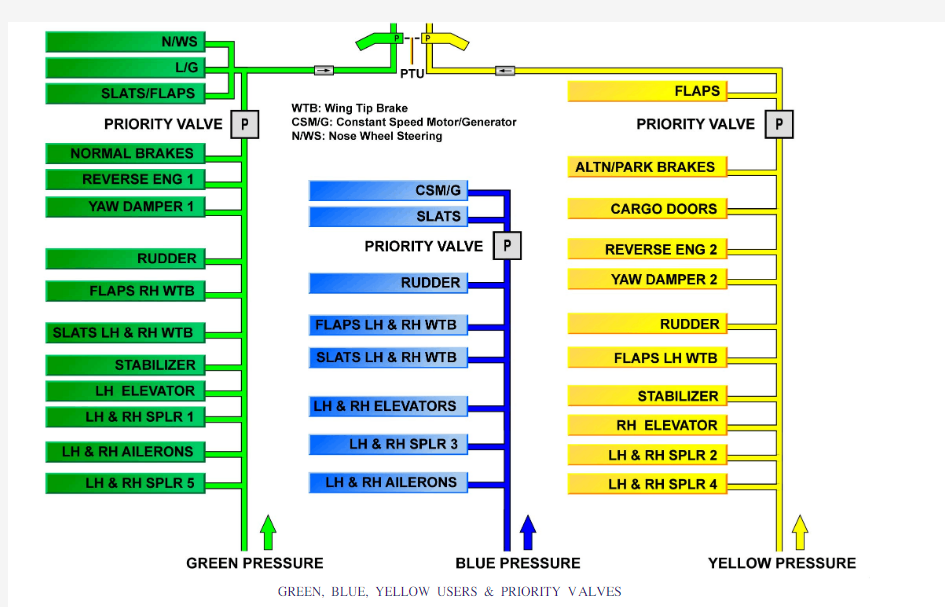
GREEN, BLUE, YELLOW USERS
The three independent hydraulic systems respectively supply the users indicated on the diagram. Between these systems, the users are shared in order to ensure the aircraft control, even if only one hydraulic system is inoperative. On the blue hydraulic system, the Constant Speed
Motor/Generator (CSM/G) is used to provide aircraft electrical power in case of emergency.
PRIORITY V ALVES
In the event of low hydraulic pressure, the priority valves maintain the operation of essential systems by cutting off hydraulic power to heavy load users.
GREEN, BLUE, YELLOW USERS & PRIORITY V ALVES
HYDRAULIC POWER LEVEL 2 (2)
SYSTEM OVERVIEW
On the green system the normal source of pressure is the Engine Driven Pump (EDP) and as auxiliary source the Power Transfer Unit (PTU). On the blue system the normal source of pressure is the electrical pump (E-Pump) and as auxiliary source the Ram Air Turbine (RAT). NOTE:The blue electric pump can be used as an auxiliary power source for maintenance purposes on ground.
On the yellow system the normal source of pressure is the Engine Driven Pump (EDP) and as auxiliary sources the Power Transfer Unit (PTU) and the electric pump (E- Pump).
NOTE:The yellow system also has a hand pump dedicated to cargo door operation.
PTU
The Power Transfer Unit (PTU) is an auxiliary pressure supply for either the green or yellow systems without transfer of fluid between the two systems.
It operates automatically if there is a delta pressure of 500psi between the green / yellow or yellow / green hydraulic systems.
The side operating as a pump will take fluid from its associated
reservoir and provide an output through the PTU manifold to the HP manifold.
The motor side is supplied from the HP manifold through the PTU manifold, and is connected to the return system.
Each section of the PTU has a case drain connection to the return system.
RAT
The Ram Air Turbine (RAT) is an auxiliary pressure supply for the blue system, and for the emergency electrical power CSM / G.It can be deployed automatically or manually depending on the failure conditions.
The RAT is locked when extended.
An index lock mechanism will only permit RAT stowage if the blades are properly aligned.
It also prevents rotation when stowed. The index lock will release at approximately 5 degrees from the full extension position. Extension is by spring force. Retraction (stowage) is by blue hydraulic pressure.
Up lock release is by solenoid operation.
Down lock release is by hydraulic pressure.
SYSTEM OVERVIEW - PTU & RAT
HYDRAULIC POWER LEVEL 2 (2)
SERVICING
RESERVOIR AIR PRESSURIZATION
All three reservoirs are pressurized to 50 psi to prevent pump
cavitations.
The non-return valves in each reservoir supply manifold, make sure that the pressure will be maintained for up to 12 hours after engine shutdown on ground, and for up to 3 hours following a failure of the air supply in flight.
Each reservoir has a depressurization valve on its associated service panel. For long time depressurization, a depressurization tool may be installed on the depressurization valve.
A 77 psi pressure relief valve is installed onto the supply manifold at
each reservoir.
All tree reservoirs are pressurized from Engine 1 for normal supply and the bleed air system for alternate supply at 43 psi.
The air pressurization manifold has a ground supply connection.
It is put into the blue hydraulic bay and regulates normal or ground supply to 50 psi.
Cleanable filters have clogging indicators.
There are two water drains, one is automatic after engines and APU shut down, and the other is manually operated.
After maintenance on the hydraulic system, the reservoir pressurization can be done via a pneumatic ground cart connected to the reservoir pressure unit, the APU, or the pneumatic system ground connection.
SERVICING - RESERVOIR AIR PRESSURIZATION
HYDRAULIC POWER LEVEL 2 (2) SERVICING (continued)
FLUID LEVEL CHECK
The following Aircraft Configuration is needed for a correct fluid level check and servicing:
- the speed brakes and spoilers must be retracted,
- the thrust reversers stowed,
- the cargo doors closed,
- all system accumulators empty of fluid,
- the accumulators pre-charge pressure must be checked,
- the reservoirs pressurized with air,
- the landing gear must be in down position with the landing gear doors closed (one door may be open),
- and the brake accumulator may be pressurized with fluid.
SERVICING - FLUID LEVEL CHECK
HYDRAULIC POWER LEVEL 2 (2)
SERVICING (continued)
RESERVOIR FILLING
Switch on the yellow electric pump to make sure that the brake
accumulator is pressurized, then switch the pump off.
Connect the selected servicing source to the green servicing panel.
When the panel hand pump is used, connect the hose to the hand pump and insert it into the fluid container, and then install the pump handle.
The handle is stowed at the yellow servicing panel.
When the external pump is used, connect the lower filling port and set the minimum flow, do not exceed 435 psi.
Then select the reservoir to be filled, confirming associated light is ON, and fill with fluid to the upper end of the scale.
NOTE:Over filling the reservoir will result in an inadequate
pressurization.
The reservoir level is also affected by large changes in ambient
temperature. For every 10 °C change, the green volume changes by
0.85 Lt, the blue volume changes by 0.51 Lt, and the yellow volume
changes by 0.64 Lt.
SERVICING - RESERVOIR FILLING
HYDRAULIC POWER LEVEL 2 (2)
SERVICING (continued)
BLEEDING
If you have filled the reservoir after:
- maintenance,
- or removal/installation of large hydraulic components,
- or hydraulic fluid low level (loss of the hydraulic system),
- or high loss of hydraulic fluid,
Do the related bleeding procedure to make sure that the quantity of hydraulic fluid in the system is correct.
After maintenance of the hydraulic system upstream of the EDP,
loosen the nut of the case drain hose so that the air (or hydraulic fluid mixed with air bubbles) comes out of the connection. Check:
- make sure that the air pressure in the reservoir of the associated hydraulic system is not less than 50 psi (if necessary, pressurize the reservoir),
- read the gauge of the associated reservoir and make a note of the fluid level,
- depressurize the reservoir of the associated hydraulic system,
- after 5 minutes, read the gauge again and make a note of the level, - compare both levels,
- if the difference between both levels is more than 2 liters, do the bleeding procedures again until the result is satisfactory.
SERVICING - BLEEDING
HYDRAULIC POWER LEVEL 2 (2)
SERVICING (continued)
HIGH PRESSURE (HP), CASE DRAIN, AND LOW
PRESSURE (LP) FILTERS
The three Hydraulic Systems have:
- a HP filter in the pressure line, in the reservoir filling system, and the normal braking system,
- an LP filter in the return line,
- a case drain filter in the case drain line of the EDP's.
The HP and the case drain filters have a red clogging indicator, which pops out when the filter is clogged (dirty).
The LP filters have a replaceable filter elements and a by-pass system.
This Page Intentionally Left Blank
HYDRAULIC POWER LEVEL 2 (2)
SERVICING (continued)
ACCUMULATORS
Each system has an accumulator, located in their associated hydraulic bays.
The yellow brake system has an accumulator for emergency braking and parking brake.
The nitrogen pre-charge is adjusted at the accumulator in accordance to the ambient temperature.
On system pressurization the accumulators will each take
approximately 1 Lt. of fluid.
Each accumulator has a nitrogen pressure indicator.
SERVICING - ACCUMULATORS
HYDRAULIC POWER LEVEL 2 (2)
SERVICING (continued)
EXTERNAL LEAK TEST OF COMPONENTS
A leak is the quantity of fluid that comes out of a component and that
is sufficient to become a drop or drops, or will possibly become a drop of approximately 20 drops =1 cc, and 75600 drops =1 gallon.
A leakage is a quantity of fluid on the surface of a component that is
not sufficient to become a drop.
A stain is an area on the surface of a component that has a different
color. It is usually caused when fluid leakage becomes dry on the component surface after a high temperature operation.
For a correct analysis of component leak rates, you must obey the subsequent steps:
- the seal obtained at hydraulic tube connections is obtained on
metal-to-metal surfaces. If a leak cannot be stopped by tightening the nut to the specified torque, the joint is probably defective and should be repaired.
- when possible, activate components for some cycles before carrying out the external leakage check.
- dynamic seals are easy to examine for leakage while in the static condition because pistons, slide valves and swivel joints move only during a short time interval. Many components cannot be obviously monitored during operation.
- by following the AMM procedure operate the related component, - after operation, inspect the component. If there is a sign of any
external leakage, compare the quantity of leakage with the values given in the AMM table for specified limits.
SERVICING - EXTERNAL LEAK TEST OF COMPONENTS