ILI-S-E3中文资料

12 Clintonville Road, Northford, CT 06472-1610 USA ? Tel: (203) 484-7161 ? Fax: (203) 484-7118
Specifications are for information only, are not intended for installation purposes, and are subject to change without notice. No responsibility is assumed by Gamewell-FCI for their use.
ILI-MB-E3Series
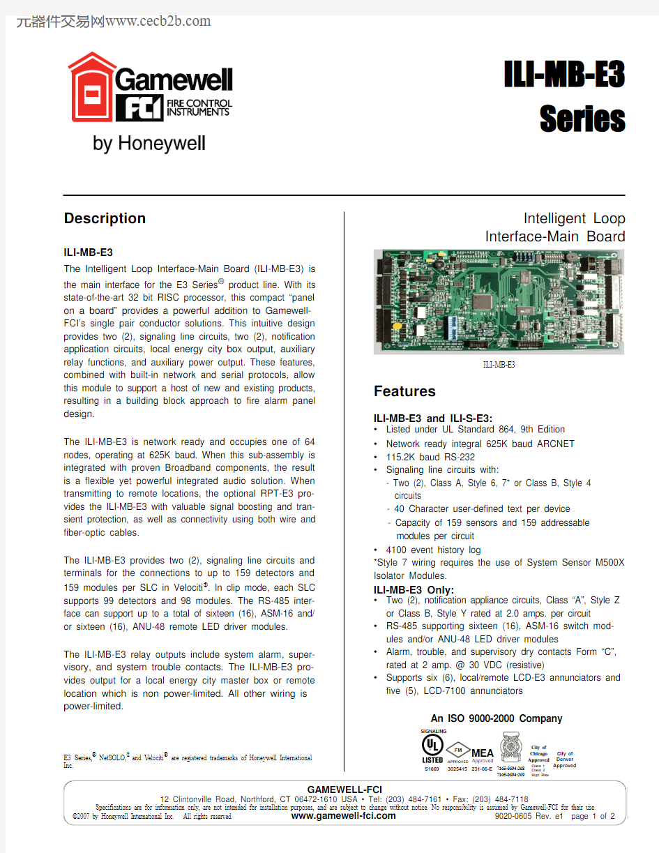
ILI-MB-E3
Features
SIGNALING
S1869
7165-0694:268
7165-0694:269
GAMEWELL-FCI
12 Clintonville Road, Northford, CT 06472-1610 USA ? Tel: (203) 484-7161 ? Fax: (203) 484-7118
9000-0605 Rev. e1 page 2 of https://www.sodocs.net/doc/eb8041778.html,
ILI-S-E3
ILI-S-E3
The Intelligent Loop Interface - Expansion Board (ILI-S-E3)provides the E3 Series control panel with two (2), additional signaling line circuits. The layout is similar to the ILI-MB-E3except a number of components are omitted. The ILI-S-E3occupies one node on the Broadband network. The ILI-S-E3 provides two (2), signaling line circuits and terminals for the connections to up to 159 detectors and 159 modules per SLC in Velociti mode. In clip mode, each SLC supports 99 detectors and 98 modules.
Installation
Typically, the ILI-MB-E3 or ILI-S-E3 can be mounted in the following E3 Series cabinets:?Cabinet B and D, backbox
?Cabinet C, INX-E3 sub-assembly plate ?Cabinet C, INCC-E3 sub-assembly plate
For instructions on installing the ILI-MB-E3 or ILI-S-E3,refer to the E3 Series ? Expandable Emergency Evacuation Installation/Operating Manual, Part Number: 9000-0574,the ILI-MB-E3 Installation Instructions, Part Number: 9000-0579, or the ILI-S-E3 Installation Instructions, Part Number:9000-0569.
Specifications
Operating Voltage:
24 VDC FWR
(from PM-9 Power Supply)
Operating Current:0.081 amp.Alarm Current:0.150 amp. max.
Operating Temperature:32° to 120° F (0° to 49° C)Relative Humidity:0 to 93%, non-condensing
at 90° F (32° C)
SLC 40 Ohms maximum line impedance.- 0.5 μf maximum line capacitance.
Ordering Information
Model
Description
ILI-MB-E3Intelligent Loop Interface-Main Board
ILI-S-E3
Intelligent Loop Interface-Expansion Board