注射硅橡胶来提高模具的尺寸精度翻译

注射硅橡胶来提高模具的尺寸精度
P邓恩和G伯恩
机械工程学系,工程学院,都柏林大学,爱尔兰共和国
摘要:快速原型系统固有的技术局限性导致发展快速制模技术。这些技术是生产材料原型能力预期的制造过程。一个快速模具制造过程,提供了一个低成本,快速的注射成型热塑性增强硅元件制造成型。在成型周期的压力和温度下的研究模具变形情况和组件生产遭受损失的尺寸精度。
以分析和实验研究进行了量化的尺寸精度,由过程中产生的成分,确定成型参数,有助于减少对尺寸精度的损失。模具在各种成型条件中制作一个立体主从模式和用于高冲击聚苯乙烯注塑模具零件。模压部件生产是典型的与一对超大的尺寸精度损失为0.3 ± 0.6毫米。两个参数,即注射压力和模具温度等发现有一对尺寸精度的影响。
注射压力会使模腔扩大零部件制造的结果是超大的。在一个组件注射压16MPa产生的平均值0.34毫米(1.3百分之)宽过大,0.36毫米(百分之11.3)在深度过大。这些在一个生产注射压力20MPa的情况下产生平均的0.45特大(百分之1.8)宽度和0.59毫米(百分之18.6)的深度,由于模具温度的升高导致模具型腔尺寸减少,这是因为橡胶模具是在一个受限制金属模架。橡胶模具扩展到腔自由空间,组件在50,70和90°的生产模具温度在以平均过大宽度分别为0.37毫米(百分之1.5),0.34毫米(百分之1.3)和0.20(百分之0.8)。
关键词:真空铸造,快速模具,模具硅胶
符号
d 深度(毫米)
D 宽度(毫米)
w 浇口距离(毫米)
1简介
喷射注塑材料和工业的快速发展让业内人士设计和制造的组件越来越复杂[1]。
与之相关的组件都是用一样的复杂的模具制造的精度要求。因此,设计制造和生产注塑模具都是费时而且价格昂贵。因此,重要的评价进行构件设计彻底关于性能和制造生产加工昂贵的承诺之前[2]。通常该评估值得指的是制造取得的原型组件。在此领域的产品设计,该术语原型一般指物理模型体现了一些或所有的元素的一种产品。原型可以分为四个类:
(a)简单的设计理念申述
(b)规模的非功能性模型原型通常用来交流的具体的设计理念,
(c)实验原型的主要工作体现了功能模型的设计元素
(d)全部工作, 完全功能模型原型设计,应该是在技术上是完美的[3]。
有三种主要的路线了样机的制造的设计步骤:例如加工、快速成型和快速模具。加工的应用和快速成型技术来支持原型制造建立。然而,原型生产不具有相同的材料和工艺特点,塑造组件。快速加工技术克服这些限制,包括来自低成本的制造模具原型[4]。
使用最广泛的快速制模技术是真空铸造,因为它提供低成本的能力,在相对短的时间内花最小的副本费用。这一过程涉及到一个制造硅橡胶模具从主模式。模具在制造原型真空浇注型用的是聚氨酯材料[5]。使用的优越性橡胶模具材料包括易于加工模具制造、复制的细节和纹理和弹性,允许塑造组件可以除去模具而不引起的任何损坏,模具或塑造组成部分。后者
的意义上来说,一个特别的问题对许多低成本的快速加工技术。硅橡胶模具一般只能够生产小批量原型。复杂的功能的模具原型寿命是20至30。事以后、模具领域开始剥离、原型是可由变形或丢失的特点。不复杂的特点的原型模具寿命可高达60。
虽然被广泛使用,真空浇注不提供完整的解决方案的材料和工艺限制加工和快速原型技术。的硅橡胶低刚度限制材料的范围可处理那些可重力铸造;通常是聚氨酯使用。需要注入热塑性工程塑料的压力造成过多的硅胶模具变形。因此,这个过程是唯一能生产在原型的复制品的材料由低压铸造,而非注射(高压)成型过程。为了克服这些局限性,增强硅成型过程中也可使用。这一过程涉及用金属硅橡胶浸渍颗粒改善填料的橡胶材料的刚度和允许注射成型热塑性塑料。
2增强硅成型工艺
2.1材料
所用的材料是一次成型级硅橡胶浸渍与铁粉颗粒填料。该铁粉末平均粒径为2.6毫米到一个1.1毫米的标准差。硅橡胶和铁粉混合在按重量1:1的比例。该填料的选择和使用材料的比例是基于Venus et al的工作。[6]研究了填料的比对最后的加工性能和填充硅橡胶的力学性能。发现使用一个1:1的比例提供了一个良好的平衡混合浇注性之间的加工过程中作为固化材料的刚度颗粒。这颗粒硅橡胶材料被称为高硅橡胶。
进行对比试验,定量研究了填料的影响之外的力学性能的物质。压缩试验显示平均涨幅必须在应力应变材料到¢0.6应力的大约49%。压缩试验符合BS 903:部分A4纸,柱状的样本(直径29毫米,长度12.5毫米)使用四个初步负荷周期为10毫米/分钟恒位移率占应力软化效应(马林斯效应)。进行了硬度测试按照BS 903:部分有所增加A26在硬度的近似于24个百分点为4290邵氏硬度材料为53.4邵氏硬度[7]。
2.2加工
模具材料的处理包括五个阶段:对模具材料的成分分析,主要脱气搅拌,连铸,二次脱气,材料固化。
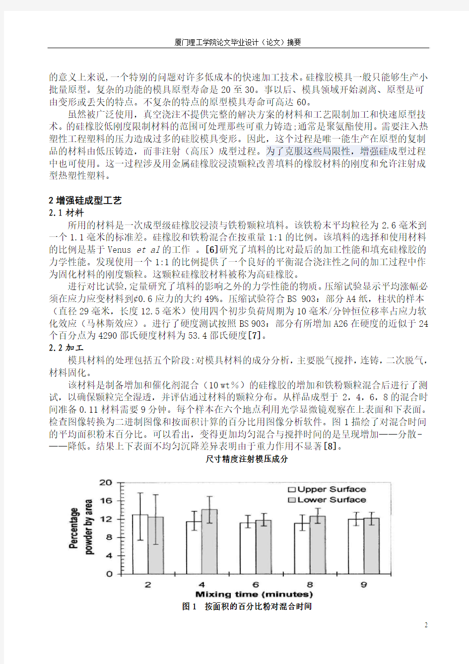
该材料是制备增加和催化剂混合(10 wt%)的硅橡胶的增加和铁粉颗粒混合后进行了测试,以确保颗粒完全湿透,并评估通过材料的颗粒分布。从样品成型于2,4,6,8的混合时间准备0.11材料需要9分钟。每个样本在六个地点利用光学显微镜观察在上表面和下表面。检查图像转换为二进制图像和按面积计算的百分比用图像分析软件。图1描绘了对混合时间的平均面积粉末百分比。可以看出,变得更加均匀混合与搅拌时间的是呈现增加——分散-——降低。结果上下表面不均匀沉降差异表明由于重力作用不显著[8]。
尺寸精度注射模压成分
图1 按面积的百分比粉对混合时间
在混合组分,空气混合和滞留的杂质必须清除。这是通过真空脱气必须进行的工作。进行测试,确定最低真空脱气时间。根据样品生产的范围从0到20分钟在740mmHg的各种真空时间。从而获得样品切片的数量和位置的空气夹杂图像分析。结果表明,没有明显杂质的空气样本,需要经过20分钟的真空脱气时间。
一旦空气杂质被删除,材料转换为最终形式。铸造是在室温进行温度和大气压力下进行的。第二个阶段是进行脱气后的材料处理。这是为了确保在铸造阶段去除可能导致任何进一步的空气又夹杂其他的物质。最后,制造商的建议固化材料在室温下24小时[9]。
3实验程序
3.1模具设计与制造
选一个简单的矩形组成的80毫米*25.4毫米*3.175毫米。该组件是填补通过直径3.5毫米的,长25毫米的手肘抛物线,输入一个偏心圆环结束门指令。组件几何形状与水口配置如图2a。
图2(a)元件的几何尺寸精度的调查(b)模具设计中使用
强化硅橡胶插入金属模具框架如图2b。模具是铸造生产的有机硅橡胶±金属粉末对主图案组合形成的。一个解决了一层厚度的模型在SL5170环氧树脂0.15mm作为主动模式。模具包括一个简单的两板模配置与平面分模线。分模线选择了这样的腔包让一个模具使用一半,让平面金属板使用另一半。 K型热电偶的两个分别插入硫化橡胶的两个沿腔长的位置,约15毫米的腔两端,2至8毫米以下的腔面。这些是用来监测模具的温度。人们不需要将产品系统为材料弯曲的时间担心, 模具仅为low-volume制造,可以有效的去除成型或冷却系统,因此周期时间并不苛刻。橡胶模具被三个发泄渠道分割,最后的橡胶浇不足问题已解决。
3.2注塑
注射高抗冲聚苯乙烯成型使用了横向夹紧用半自动立式柱塞式成型机。柱塞是由气缸驱动。桶使用带加热加热器和模具筒加热用加热器。一共有45个部件成型,如表1所述。用于模具组件的初始设置如表2。这些最初的设置是从制造商那里获得的数据,文献和成型试验进行类似的组件与模具的几何形状[8,10,11]是用金属加工出来。
表1实验计划
数量成型参数
5 初始设置列于表2
5 保持时间减少到初始设置2秒
5 初始设置保持时间增加至10秒
5 注射温度降低到初始设置185度
5 注射温度初始设置减少到200度
5 注射压力降低到12.5MPa的初始设置
5 喷油压力提高到20MPa的初始设置
5 模具温度减少到50度的初始设置
5 模具温度提高到90度的初始设置
表2参数设置初步成型
注射压力16MPa
夹紧压力12MPa
模具温度70 °
注塑温度215 °
注射时间1s/全程
保持时间5s
冷却时间120s
停腔时间120s
铅球重量8.5g
实验计划是根据不同的四个成型参数。参数即持有时间,注射温度,注射压力和模具温度,被选为他们已知的一对尺寸精度[10]。由于硅橡胶增强的有限的生命,所以模具一起进行全部析因试验的四个参数是不可行的。
3.3测量程序
用千分尺沿长度不同点测量成型的宽度和深度元件。宽度测量和深度要有九个10mm的间隔的长度位置。测量深度时,和宽度要有九个10mm间隔长度长度位置。
4结果与讨论
误差线代表在任何情况下获得的最大值和最小值。
4.1保持时间
图3 平均宽度和保持时间在三个不同的组件生产的模压深度测量
表3的形式显示的是特殊的组件生产的超大值。对于曲线的宽度的情况下,可以看出腔(30毫米 (一)中部地区是受由于模具加热和变形的结果; (二)该腔中部地区较差力的支持,所以周围的物质受力变形更严重。 深度曲线的总趋势与该地区靠近注入点(0mm 这些组件生产采用2秒保持时间导致充填不足。对于(D> 55毫米),这是最清楚地看到从深度的测量结果在深度低于标准线。这些组件生产保持时间在5秒被认为是可以接受的。保持时间要充分包装模具,因此介于2--5秒该和5--10秒保持时间的结果是相似的。5秒和10秒组件的宽度平均最大相差是0.03 到0.06毫米。宽度与深度的结果相似,平均差异为0.03及0.05mm的最大差异。这种相似性水平,大大利于分散,且表明了超过5秒的时间并没有对尺寸精度有所影响。 4.2注射温度 在不同温度下产生的组件注入的结果与保持时间的结果图(4)相似。注射温度的变化并没有对元器件的尺寸精度产生影响。宽度之间的平均差额的组件在热注射温度200,215和230°时是0.04mm到0.08mm。与深度的结果相试,平均值也在0.03mm到0.06mm。 尺寸精度注射模压成分 图4 平均宽度和温度三个注塑成型部件生产的深度测量 4.3注射压力 各种注塑压力产生的成分的结果列于图5。最重要的一点是曲线之间的差异。这突出表明,注射压力对模塑组件尺寸精度有影响。组件的尺寸注射压力12.5MPa下低于在该地区50至60。这相当于注射压力下,填补不足,包装模具型腔不完全。因此,有一短射相似的情况下,采用2的时间。在16MPa压力下注射,发现成功地克服了填充和模腔包装这个问题。在16MPa生产的部件是由一个0.34毫米(1.3%)的平均深度和一个0.36毫米(11.2%)的平均宽度组合成的。注射压力为20MPa的结果显示,从所需标准尺寸有进一步的偏差,这些组件是由一个0.45毫米(1.8%)的平均深度,一个0.59毫米(18.4%)的平均宽度组合成的。 图5 平均的宽度和深度测量元件生产塑造三个注射压力 4.4模具温度 在不同温度下的模具生产的零件的结果如图6所示。需要注意的是,模具的温度在三个组成部分产生的宽度差,各成分的平均宽度分别为25.77毫米,25.74毫米和25.60毫米,模具温度50°,70°和90 °。总的趋势是,越来越多的组件宽度与模具温度降低。这是由于橡胶模具的热膨胀使空腔尺寸减少的结果。宽度曲线的形式和以前观察到的不同。在较低的模具温度为50 °的宽度与该地区靠近注入点更大。这是和模具加热同时进行所不足的。该材料进入模具冷却速度过快,阻碍了模具型腔填充。这导致了在注射压力下更大程度上提高对模具型腔的变形材料的观测。 图6 平均宽度和三个生产成型模具温度测量元件的深度 4.5组成部分结果摘要成型 总体结果进行了总结如图7所示,平均宽度和深度结果为主要成型测试。结果清楚地说 明了不同的成型参数的影响,并表明注射压力和模具温度变化对尺寸精度有影响,而不是注 射温度和保持时间。 图7 摘要主要成型试验结果表示,由一个白色条状表明成型的短射 5结论 测量矩形样品*25.4毫米* 80毫米*3.175毫米的组件,为塑造下高抗冲聚苯乙烯各种使用柱塞式成型机的提供条件。通过对这些组件进行测量,发现它比一般的0.3 ± 0.6毫米的尺寸精度损失小。在不同的(保持时间,注射温度,模具温度和注射压力)四个参数下,发 现有一对尺寸精度的对其有影响。那就是注射压力和模具温度。 对于注射压力,不同的情况下,人们发现注射压力的增加导致了在元件尺寸的增加,从 而提高尺寸精度的损失。在模具温度的情况下,发现增加模具的温度导致对尺寸精度的改善。模具温度提高使得硅橡胶更容易插入到模具结构。即在热膨胀模具的模具变形的压力下,这 结果会降低腔大小同时成型组件的更准确。 本次调查的重点是确定的成型参数,有助于提高尺寸精度在硅胶成型过程的损失。随着 占主导地位的成型参数的知识是设想的有限元模型,以发展预测,并最终以补偿在这个过程 中的尺寸精度的损失为基础。建立有限元模型的主要优点是能够预测更复杂的元件几何尺寸 的尺寸精度的损失。 鸣谢 作者们希望获得爱尔兰的先进制造技术计划先进的技术和科学与创新首长爱尔兰企业的 支持。 参考文献 1 Wang, K. and Zhou, J. A concurrent-engineeringapproach towards the online adaptive control of injection moulding process. Ann. CIRP, 2000, 49(1), 379±382. 2 Ullman, D. The Mechanical Design Process, 2nd edition, 1997 (McGraw-Hill, New York). 3 Dieter, G. Engineering Design: A Materials and Processing Approach, 3rd edition, 2000 (McGraw-Hill, New York). 4 Michaeli, W., Brinkmann, S. and Langen, M. How close are moulded parts from RT moulds from series production? Kunsto. e Plastic Europe, November 1996, 9±10. 5 Rosochowski, A. and Matuszak, A. Rapid tooling: state of the art. J. Mater. Processing Technol., 2000, 106, 191±198. 6 Venus, A., van de Crommert, S. and O’Hagan, S. The feasibility of silicone rubber as an injection mould tooling process using rapid prototyped patterns. In Proceedings of the Second National Conference on Developments in Rapid Prototyping and Tooling (Ed. G. Bennett), Buckingham College, 1997, pp. 105±109 (Mechanical Engineering Publications Limited, London). 7 Dunne, P. and Byrne, G. The e. ect of mould heating on the accuracy of rapid tooling. In Proceedings of the 16th International Conference on Computer-Aided Production Engineering (CAPE 2000), The University of Edinburgh, August 2000, pp. 565±574. 8 Dunne, P. An investigation into the dimensional accuracy of injection moulded components produced in a silicone rubber mould. PhD thesis, University College Dublin, May 2002. 9 MCP. Vacuum Casting TechniqueDA Guide for New Users, Technical Publication 1, June 1995 (MCP Equipment). 10 Bryce, D. Plastic Injection MouldingDManufacturing Process Fundamentals, Vol. I, Fundamentals of Injection Moulding Series, 1996 (Society ofManufacturing Engineers, Dearborn, Michigan). 11 BASF. Polystyrol 473D Product Information Sheet, 1998 (BASF Aktiengessallschaft). DIMENSIONAL ACCURACY OF INJECTION-MOULDED COMPONENTS 57 B10003 中英文对照外文翻译文献 (文档含英文原文和中文翻译) 外文: The development of plastic mould China's industrial plastic moulds from the start to now, after more than half a century, there has been great development, mold levels have been greatly enhanced. Mould has been at large can produce 48-inch big-screen color TV Molded Case injection mold, 6.5 kg capacity washing machine full of plastic molds, as well as the overall car bumpers and dashboards, and other plastic mould precision plastic molds, the camera is capable of producing plastic mould , multi-cavity mold small modulus gear and molding mold. --Such as Tianjin and Yantai days Electrical Co., Ltd Polaris IK Co. manufactured multi-cavity mold VCD and DVD gear, the gear production of such size precision plastic parts, coaxial, beating requirements have reached a similar foreign the level of product, but also the application of the latest gear design software to correct contraction as a result of the molding profile error to the standard involute requirements. Production can only 0.08 mm thickness of a two-cavity mold and the air Cup difficulty of plastic doors and windows out of high modulus, and so on. Model cavity injection molding manufacturing accuracy of 0.02 to 0.05 mm, surface roughness Ra0.2 μ m, mold quality, and significantly increase life expectancy, non-hardening steel mould life up to 10~ 30 million, hardening steel form up to 50 ~ 10 million times, shorten the delivery time than before, but still higher than abroad,and the gap between a specific data table. Process, the multi-material plastic molding die, efficient multicolor injection mould, inserts exchange structure and core pulling Stripping the innovative design has also made great progress. Gas-assisted injection molding, the use of more mature technologies, such as Qingdao Hisense Co., Ltd., Tianjin factorycommunications and broadcasting companies, such as moldmanufacturers succeeded in 29 ~ 34-inch TV thick-walled shell, as well as some parts on the use of gas-assisted mould technology Some manufacturers also use the C-MOLD gas-assisted software and achieved better results. Prescott, such as Shanghai, such as the new 模具英语专业术语 模具述语 一、入水:gate 进入位: gate location 水口形式:gate type 大水口:edge gate 细水口: pin-point gate 水口大小:gate size 转水口: switching runner/gate 唧嘴口径: sprue diameter 二、流道: runner 热流道: hot runner,hot manifold 热嘴冷流道: hot sprue/cold runner 唧嘴直流: direct sprue gate 圆形流道:round(full/half runner 流道电脑分析:mold flow analysis 流道平衡:runner balance 热嘴: hot sprue 热流道板:hot manifold 发热管:cartridge heater 探针: thermocouples 插头: connector plug 插座: connector socket 密封/封料: seal 三、运水:water line 喉塞:line lpug 喉管:tube 塑胶管:plastic tube 快速接头:jiffy quick connector plug/socker 四、模具零件: mold components 三板模:3-plate mold 二板模:2-plate mold 边钉/导边:leader pin/guide pin 边司/导套:bushing/guide bushing 中托司:shoulder guide bushing 中托边L:guide pin 顶针板:ejector retainner plate 托板: support plate 螺丝: screw 管钉:dowel pin 开模槽:ply bar scot 内模管位:core/cavity inter-lock 顶针: ejector pin 司筒:ejector sleeve 司筒针:ejector pin 推板:stripper plate 缩呵:movable core,return core core puller 扣机(尼龙拉勾):nylon latch lock 斜顶:lifter 模胚(架): mold base 上内模:cavity insert 下内模:core insert 行位(滑块): slide 镶件:insert 压座/斜鸡:wedge 耐磨板/油板:wedge wear plate 压条:plate 撑头: support pillar 唧嘴: sprue bushing 挡板:stop plate 定位圈:locating ring 锁扣:latch 扣鸡:parting lock set 推杆:push bar 栓打螺丝:S.H.S.B 顶板:eracuretun 活动臂:lever arm 分流锥:spure sperader 水口司:bush 垃圾钉:stop pin 隔片:buffle 弹弓柱:spring rod 弹弓:die spring 中托司:ejector guide bush 中托边:ejector guide pin 镶针:pin 销子:dowel pin 波子弹弓:ball catch 喉塞: pipe plug Injection Molding The basic concept of injection molding revolves around the ability of a thermoplastic material to be softened by heat and to harden when cooled .In most operations ,granular material (the plastic resin) is fed into one end of the cylinder (usually through a feeding device known as a hopper ),heated, and softened(plasticized or plasticized),forced out the other end of the cylinder, while it is still in the form of a melt, through a nozzle into a relatively cool mold held closed under pressure.Here,the melt cools and hardens until fully set-up. The mold is then opened, the piece ejected, and the sequence repeated. Thus, the significant elements of an injection molding machine become: 1) the way in which the melt is plasticized (softened) and forced into the mold (called the injection unit); 2) the system for opening the mold and closing it under pressure (called the clamping unit);3) the type of mold used;4) the machine controls. The part of an injection-molding machine, which converts a plastic material from a sold phase to homogeneous seni-liguid phase by raising its temperature .This unit maintains the material at a present temperature and force it through the injection unit nozzle into a mold .The plunger is a combination of the injection and plasticizing device in which a heating chamber is mounted between the plunger and mold. This chamber heats the plastic material by conduction .The plunger, on each stroke; pushes unbelted plastic material into the chamber, which in turn forces plastic melt at the front of the chamber out through the nozzle The part of an injection molding machine in which the mold is mounted, and which provides the motion and force to open and close the mold and to hold the mold close with force during injection .This unit can also provide other features necessary for the effective functioning of the molding operation .Moving 模具术语英文翻译 模具术语英文翻译 根据国家标准,以下为部分塑料模具成形术语的标准翻译。 动模 Movable Mould Moving Half 定模座板 Fixed Clamp Plate Top Clamping Plate Top Plate 动模座板 Moving Clamp Plate Bottom Clamping Plate Bottom Plate 上模座板 Upper Clamping Plate 下模座板 Lower Clamping Plate 凹模固定板 Cavity-retainer Plate 型芯固定板 Mould Core-retainer Plate 凸模固定板 Punch-retainer Plate 模套 Die Body Die Sleeve Die Blank 支承板 Backing Plate Support Plate 垫块 Spacer Parallel 支架 Ejector Housing Mould Base Leg 模头 Die Head 根据国家标准,以下为部分压铸模具术语的标准翻译。 压力铸造模具 Die-Casting Die 压铸模零部件 定模 Fixed Die Cover Die 定模座板 Fixed Clamping Plate 定模套板 Bolster Fixed Die 动模 Moving Die Ejector Die 动模座板 Moving Clamping Plate 直流道 Sprue 横流道 Runner 内浇口 Gate 模具分类 Injection Mold 注塑模 Plastic Rubber Mould 塑胶模 Rubber Molding 橡胶成形 Hot Chamber Die Casting 热室压铸 Sand Mold Casting 砂模铸造 Extrusion Mold 挤出模 Multi-Cavity Mold 多模穴模具 Stack Mold, Stack Injection Mould 叠层模 (此文档为word格式,下载后您可任意编辑修改!) 冷冲模具使用寿命的影响及对策 冲压模具概述 冲压模具--在冷冲压加工中,将材料(金属或非金属)加工成零件(或半成品)的一种特殊工艺装备,称为冷冲压模具(俗称冷冲模)。冲压--是在室温下,利用安装在压力机上的模具对材料施加压力,使其产生分离或塑性变形,从而获得所需零件的一种压力加工方法。 冲压模具的形式很多,一般可按以下几个主要特征分类: 1?根据工艺性质分类 (1)冲裁模沿封闭或敞开的轮廓线使材料产生分离的模具。如落料模、冲孔模、切断模、切口模、切边模、剖切模等。 (2)弯曲模使板料毛坯或其他坯料沿着直线(弯曲线)产生弯曲变形,从而获得一定角度和形状的工件的模具。 (3)拉深模是把板料毛坯制成开口空心件,或使空心件进一步改变形状和尺寸的模具。 (4)成形模是将毛坯或半成品工件按图凸、凹模的形状直接复制成形,而材料本身仅产生局部塑性变形的模具。如胀形模、缩口模、扩口模、起伏成形模、翻边模、整形模等。2?根据工序组合程度分类 (1)单工序模在压力机的一次行程中,只完成一道冲压工序的模具。 (2)复合模只有一个工位,在压力机的一次行程中,在同一工位上同时完成两道或两道以上冲压工序的模具。 (3)级进模(也称连续模) 在毛坯的送进方向上,具有两个或更多的工位,在压力机的一次行程中,在不同的工位上逐次完成两道或两道以上冲压工序的模具。 冲冷冲模全称为冷冲压模具。 冷冲压模具是一种应用于模具行业冷冲压模具及其配件所需高性能结构陶瓷材料的制备方法,高性能陶瓷模具及其配件材料由氧化锆、氧化钇粉中加铝、错元素构成,制备工艺是将氧化锆溶液、氧化钇溶液、氧化错溶液、氧化铝溶液按一定比例混合配成母液,滴入碳酸氢铵,采用共沉淀方法合成模具及其配件陶瓷材料所需的原材料,反应生成的沉淀经滤水、干燥,煅烧得到高性能陶瓷模具及其配件材料超微粉,再经过成型、烧结、精加工,便得到高性能陶瓷模具及其配件材料。本发明的优点是本发明制成的冷冲压模具及其配件使用寿命长,在冲压过程中未出现模具及其配件与冲压件产生粘结现象,冲压件表面光滑、无毛刺,完全可以替代传统高速钢、钨钢材料。 冷冲模具主要零件冷冲模具是冲压加工的主要工艺装备,冲压制件就是靠上、下模具的相对运动来完成的。 加工时由于上、下模具之间不断地分合,如果操作工人的手指不断进入或停留在模具闭合区,便会对其人身安全带来严重威胁。 1 前言 在目前激烈的市场竞争中,产品投入市场的迟早往往是成败的关键。模具是高质量、高效率的产品生产工具,模具开发周期占整个产品开发周期的主要部分。因此客户对模具开发周期要求越来越短,不少客户把模具的交货期放在第一位置,然后才是质量和价格。因此,如何在保证质量、控制成本的前提下加工模具是值得认真考虑的问题。模具加工工艺是一项先进的制造工艺,已成为重要发展方向,在航空航天、汽车、机械等各行业得到越来越广泛的应用。模具加工技术,可以提高制造业的综合效益和竞争力。研究和建立模具工艺数据库,为生产企业提供迫切需要的高速切削加工数据,对推广高速切削加工技术具有非常重要的意义。本文的主要目标就是构建一个冲压模具工艺过程,将模具制造企业在实际生产中结合刀具、工件、机床与企业自身的实际情况积累得高速切削加工实例、工艺参数和经验等数据有选择地存储到高速切削数据库中,不但可以节省大量的人力、物力、财力,而且可以指导高速加工生产实践,达到提高加工效率,降低刀具费用,获得更高的经济效益。 1.冲压的概念、特点及应用 冲压是利用安装在冲压设备(主要是压力机)上的模具对材料施加压力,使其产生分离或塑性变形,从而获得所需零件(俗称冲压或冲压件)的一种压力加工方法。冲压通常是在常温下对材料进行冷变形加工,且主要采用板料来加工成所需零件,所以也叫冷冲压或板料冲压。冲压是材料压力加工或塑性加工的主要方法之一,隶属于材料成型工程术。 冲压所使用的模具称为冲压模具,简称冲模。冲模是将材料(金属或非金属)批量加工成所需冲件的专用工具。冲模在冲压中至关重要,没有符合要求的冲模,批量冲压生产就难以进行;没有先进的冲模,先进的冲压工艺就无法实现。冲压工艺与模具、冲压设备和冲压材料构成冲压加工的三要素,只有它们相互结合才能得出冲压件。 与机械加工及塑性加工的其它方法相比,冲压加工无论在技术方面还是经济方面都具有许多独特的优点,主要表现如下; (1) 冲压加工的生产效率高,且操作方便,易于实现机械化与自动化。这是 常用模具零件中英文对照表 2005-12-19 14:51:17???中国注塑网 入水:gate 进入位:gate location 水口形式:gate type 大水口:edge gate 细水口: pin-point gate 水口大小:gate size 转水口:switching runner/gate 唧嘴口径:sprue diameter 二、流道: runner 热流道:hot runner,hot manifold 热嘴冷流道: hot sprue/cold runner 唧嘴直流: direct sprue gate 圆形流道:round(full/half runner 流道电脑分析:mold flow analysis :?[??n?l?s?s] 流道平衡:runner balance 热嘴:hot sprue 热流道板:hot manifold 发热管:cartridge heater 探针: thermocouples 插头:connector plug 插座: connector socket 密封/封料: seal 三、运水:water line 喉塞:line lpug 喉管:tube 塑胶管:plastic tube 快速接头:jiffy quick connector plug/socker 四、模具零件:mold components 三板模:3-plate mold 二板模:2-plate mold 边钉/导边:leader pin/guide pin 边司/导套:bushing/guide bushing 中托司:shoulder guide bushing 中托边:guide pin 顶针板:ejector retainer plate 托板:support plate DFM常用中英文对照 1、这个红色面在前模方向/后模方向/行位方向有倒扣。 This red surface is undercut at cavity side / core side / slider side. 2、这些红色面在前模方向/后模方向/行位方向有倒扣。 These red surfaces are undercut at cavity side / core side / slider side. 3、产品的这个位置太小,导致模具在前模方向/后模方向/行位方向有薄钢位。 This position is too small and it will bring the thin steel at cavity side / core side / slider side. 4、这些红色线是前后模/镶件/行位/斜顶分型线。 These red lines are the parting line of cavity and core / insert / slider / lifter. 5、此产品使用推板/推块顶出。 Use the stripper plate / ejector block to eject this part. 6、前模/后模斜内行位。 Inner angle slider at cavity / core side. 7、为了简化模具结构建议改变此处出模方向。 Suggest to change the draft direction of this position to make the mold structure simply. 8、最终的进胶位置根据模流分析。 Finally gate position according the mold flow analysis. 9、斜顶与后面的柱位空间太小,斜顶在运动时会干涉到柱子,请考虑移动这个柱子的位置。 This lifter intervene with the pole during ejection, please consider changing the position of the pole. 10、此处有薄钢位,强度不足而且不容易冷却。 The strength of this area is too weak and it is hard to cool because the thin steel. 11、此处有尖角,填充困难。 It is hard to fill for this area because the sharp feature. 12、此处料位太厚,会有缩水,建议减胶改善。 We suggest to reduce some wall thickness to avoid the sink mark for this position. 13、此处的行位夹线在外观面上,请确认是否接受? Please confirm whether it is acceptable to have a slider line on the visible surface? 14、建议加大拔模角,以便脱模顺利。 We suggest to enlarge the draft angle to help release the tool. 15、如果分型面此处,模具上会有尖角和刀口,对模具寿命有影响。 There are sharp edges if we set the parting line here, it will reduce the tool life. 16、此处料厚段差很大,成品表面会有应力痕,建议修改如图示。 The thickness is not equal and it will bring the stress lines on the surface, suggest to improve the part as the picture shown. 17、此大行位上有小行位,开模时小行位需先退,大行位做延时,合模时则相反。 The small slider is inside the big slider, when the mold open, the small slider need to recede first and the big slider have to postpone. When the mold close, it is contrary. 18、此处需做强顶。 This position need to force ejection. 19、由于此处没有足够空间下热咀,所以需做一个柱子进胶。 This position need to make a pole for gating because there have no enough space for hot sprue. 20、沾模, stick 济南大学泉城学院 毕业设计外文资料翻译 题目现代快速经济制造模具技术 专业机械制造及其自动化 班级专升本1302班 学生刘计良 学号2013040156 指导教师刘彦 二〇一五年三月十六日 Int J Adv Manuf Technol ,(2011) 53:1–10DOI 10.1007/s00170-010-2796-y Modular design applied to beverage-container injection molds Ming-Shyan Huang & Ming-Kai Hsu Received: 16 March 2010 / Accepted: 15 June 2010 / Published online: 25 June 2010 # Springer-Verlag London Limited 2010 Modular design applied to beverage-container injection molds The Abstract: This work applies modular design concepts to designating beverage-container injection molds. This study aims to develop a method of controlling costs and time in relation to mold development, and also to improve product design. This investigation comprises two parts: functional-ity coding, and establishing a standard operation procedure, specifically designed for beverage-container injection mold design and manufacturing. First, the injection mold is divided into several modules, each with a specific function. Each module is further divided into several structural units possessing sub-function or sub-sub-function. Next, dimen-sions and specifications of each unit are standardized and a compatible interface is constructed linking relevant units. This work employs a cup-shaped beverage container to experimentally assess the performance of the modular design approach. The experimental results indicate that the modular design approach to manufacturing injection molds shortens development time by 36% and reduces costs by 19 23% compared with the conventional ap-proach. Meanwhile, the information on Mold design and manufacture The mold is the manufacturing industry important craft foundation, in our country, the mold manufacture belongs to the special purpose equipment manufacturing industry. China although very already starts to make the mold and the use mold, but long-term has not formed the industry. Straight stabs 0 centuries 80's later periods, the Chinese mold industry only then drives into the development speedway. Recent years, not only the state-owned mold enterprise had the very big development, the three investments enterprise, the villages and towns (individual) the mold enterprise's development also quite rapid . Although the Chinese mold industrial development rapid, but compares with the demand, obviously falls short of demand, its main gap concentrates precisely to, large-scale, is complex, the long life mold domain. As a result of in aspect and so on mold precision, life, manufacture cycle and productivity, China and the international average horizontal and the developed country still had a bigger disparity, therefore, needed massively to import the mold every year . The Chinese mold industry except must continue to sharpen the productivity, from now on will have emphatically to the profession internal structure adjustment and the state-of-art enhancement. The structure adjustment aspect, mainly is the enterprise structure to the specialized adjustment, the product structure to center the upscale mold development, to the import and export structure improvement, center the upscale automobile cover mold forming analysis and the structure improvement, the multi-purpose compound mold and the compound processing and the laser technology in the mold design manufacture application, the high-speed cutting, the superfinishing and polished the technology, the information direction develops . 模具名词中英文对照表序号中文名英文名 1一、水口gate 2进水位gate location 3水口形式gate type 4大水口edge gate 5细水口pin-point gate 6水口大小gate size 7转水口switching gate 8唧嘴口径sprue diameter 9二、流道runner 10热流道hot runner 11冷流道cold runner 12唧嘴直流direct sprue gate 13圆形流道round runner 14模流分析mold flow analysis 15流道平衡runner balance 16热嘴hot sprue 17热流道板hot manifold 18发热管cartridge heater 19探针thermocouples 20插头connector plug 21插座connector socket 22密封/封料seal 23三、运水water line 24喉塞line pug 25喉管tube 26塑胶管plastic tube 27快速接头jiffy quick connector plug 28四、模具零件mold components 29三板模three-plate mold 模具名词中英文对照表 序号中文名英文名 30二板模two-plate mold 31边钉/ 导边leader pin /guide pin 32边司/ 导套bush in g/guide bush ing 33顶针板ejector retainer plate 34托板support plate 35螺丝screw 36管钉dowel pin 37开模槽ply bar score 38内模管位core/cavity inter-lock 39顶针ejector pin 40司筒ejector sleeve 41司筒针ejector pin 42推板stripper plate 43缩呵movable core 44扣机(尼龙拉勾)n yl on latch lock 45斜顶lifter 46模胚(架)mold base 47母模cavity in sert 48公模core insert 49行位(滑块)slide 50 镶件in sert 51压座/斜鸡wedge 52耐磨板/ 油板wedge wear plate 53压条plate 54撑头support pillar 55唧嘴sprue bushing 56挡板stop plate 57定位圈locating ring 58锁扣latch 模具名词中英文对照表 序号中文名英文名 59扣鸡parti ng lock set 60推杆push bar 61栓打螺丝S.H.S.B 62顶板ejector plate 63活动臂lever arm 冷冲模具使用寿命的影响及对策 冲压模具概述 冲压模具--在冷冲压加工中,将材料(金属或非金属)加工成零件(或半成品)的一种特殊工艺装备,称为冷冲压模具(俗称冷冲模)。冲压--是在室温下,利用安装在压力机上的模具对材料施加压力,使其产生分离或塑性变形,从而获得所需零件的一种压力加工方法。 冲压模具的形式很多,一般可按以下几个主要特征分类: 1.根据工艺性质分类 (1)冲裁模沿封闭或敞开的轮廓线使材料产生分离的模具。如落料模、冲孔模、切断模、切口模、切边模、剖切模等。 (2)弯曲模使板料毛坯或其他坯料沿着直线(弯曲线)产生弯曲变形,从而获得一定角度和形状的工件的模具。 (3)拉深模是把板料毛坯制成开口空心件,或使空心件进一步改变形状和尺寸的模具。 (4)成形模是将毛坯或半成品工件按图凸、凹模的形状直接复制成形,而材料本身仅产生局部塑性变形的模具。如胀形模、缩口模、扩口模、起伏成形模、翻边模、整形模等。 2.根据工序组合程度分类 (1)单工序模在压力机的一次行程中,只完成一道冲压工序的模具。 (2)复合模只有一个工位,在压力机的一次行程中,在同一工位上同时完成两道或两道以上冲压工序的模具。 (3)级进模(也称连续模)在毛坯的送进方向上,具有两个或更多的工位,在压力机的一次行程中,在不同的工位上逐次完成两道或两道以上冲压工序的模具。 冲冷冲模全称为冷冲压模具。 冷冲压模具是一种应用于模具行业冷冲压模具及其配件所需高性能结构陶瓷材料的制备方法,高性能陶瓷模具及其配件材料由氧化锆、氧化钇粉中加铝、镨元素构成,制备工艺是将氧化锆溶液、氧化钇溶液、氧化镨溶液、氧化铝溶液按一定比例混合配成母液,滴入碳酸氢铵,采用共沉淀方法合成模具及其配件陶瓷材料所需的原材料,反应生成的沉淀经滤水、干燥,煅烧得到高性能陶瓷模具及其配件材料超微粉,再经过成型、烧结、精加工,便得到高性能陶瓷模具及其配件材料。本发明的优点是本发明制成的冷冲压模具及其配件使用寿命长,在冲压过程中未出现模具及其配件与冲压件产生粘结现象,冲压件表面光滑、无毛刺,完全可以替代传统高速钢、钨钢材料。 冷冲模具主要零件 冷冲模具是冲压加工的主要工艺装备,冲压制件就是靠上、下模具的相对运动来完成的。加工时由于上、下模具之间不断地分合,如果操作工人的手指不断进入或停留在模具闭合区,便会对其人身安全带来严重威胁。 1. The undercut area where interfere with slide block need to be filled material to help the slide can move smoothly.(和滑塊干涉的倒勾請加料填平至滑塊可以順利滑動) 2. The thickening added too thick.(加肉太多) 3. The thickening area is too wide.(加肉面積太大) 4. Gate position is moved.(GATE位置移位) 5. The split line of slide block or the area of slide.(滑塊拆的位置) 6. This area is hard to be filled due to the sharp feature(此處有尖角,填充困難) 7. The strength of this area is too weak and isn’t easy to get c old due to the steel too thin. 8. ( 此處鋼材太薄,強度不足而且不容易冷卻) 9. .The semicircle of cylinder avoids designing on slide block lest it will be pulled apart or cause drag mark. 10. ( 圓柱特徵要有一半圓不可以拆在滑塊上,以免粘滑塊造成拉白,拉斷.) 11. The part will be damaged if we make lifter in this area. 12. ( 此處做斜銷在作動時會削到成品肉厚) 13. This is critical surface where is not allow to add material. 14. ( 這個面是裝配面,不能加料) 15. This thick wall area might because sink mark,Please reduce some wall thickness to improve it.) 16. ( 此處料位太厚,會有縮水,建議減料改善) 17. Please confirm whether it is critical surface or not. Please confirm whether it is acceptable to has Slide split line if we have slide in this area. 18. (此面是不是外觀面,此處做滑塊的話會有結合線,是否可以接受) 19. Please confirm whether we can reduce material to the area where have undercut as indicated to have shut off on core and cavity side. No slide block and lifter to be made. 20. (此處有倒勾,能否減料,使公母模靠破,不做滑塊和斜銷) 21. Please confirm the issues of Parting line, Gate position...Etc otherwise the lead-time will be extended. 22. (請盡快確認這種拆模方式和結構,否則會影響模期) 23. The trim mark of the gate is not visual after open the top case if the gate position is design ed like it 24. (GATE做在此處的話.蓋子打開後看不到GATE的修剪部位) 25. We would suggest to enlarging draft to help tool released.) 26. 加大拔模角,以便脫模順利) 27. There are sharp edges if set the parting line at here, It will reduce the tool life 28. (P.L面開在此處,模具上會有尖角和刀口,對模具壽命有影響) 29. If you insist that the gate position have to be as original design then we would塑料模具发展中英文对照外文翻译文献
模具专业英文术语大全
模具毕业设计外文翻译(英文+译文)
模具术语英文翻译知识讲解
模具毕业设计外文翻译7081204
冲压模具技术外文翻译(含外文文献)
常用模具零件中英文对照表
模具DFM常用中英文对照
模具专业外文文献最新
模具设计与制造外文翻译、中英文翻译、外文文献翻译
模具术语翻译
模具毕业设计外文翻译
模具英语翻译大全
相关文档
- 模具设计与制造毕业论文中英文资料外文翻译文献
- 模具发展中英文翻译
- 外文翻译--模具的发展
- 模具中英文翻译
- 模具设计和制造外文文献翻译、中英文翻译、外文翻译
- 冲压类外文翻译、中英文翻译冲压模具设计
- 模具中英文翻译 (2)
- (完整版)模具设计与制造_毕业论文中英文资料外文翻译_文献
- 模具中英文翻译
- 模具设计与制造外文翻译、中英文翻译、外文文献翻译
- 模具设计与制造中英文外文翻译文献
- 模具的发展 外文翻译 外文文献 英文文献 中英对照
- 注塑模外文翻译
- 模具工业中英文翻译
- 塑料模具发展中英文对照外文翻译文献
- 文献翻译原文-模具的历史发展
- 文献翻译-模具的历史发展
- 模具制造中英文翻译
- 模具 外文翻译 英文文献 模具的发展与趋势
- 冲压模具技术外文翻译(含外文文献)