土木工程中英文翻译

from:journal of Constructional Steel Research.V olume 59,Number 1,January 2003 Cyclic behavior of steel moment frame
connections under varying axial load and lateral displacements Abstract: This paper discusses the cyclic behavior of four steel moment connections tested under variable axial load and lateral displacements. The beam specim- ens consisted of a reduced beam section, wing plates and longitudinal stiffeners. The test specimens were subjected to varying axial forces and lateral displace- ments to simulate the effects on beams in a Coupled-Girder Moment-Resisting Framing system under lateral loading. The test results showed that the specim- ens responded in a ductile manner since the plastic rotations exceeded 0.03 rad without significant drop in the lateral capacity. The presence of the longitudin- al stiffener assisted in transferring the axial forces and delayed the formation of web local buckling.
1. Introduction
Aimed at evaluating the structural performance of reduced-beam section(RBS) connections under alternated axial loading and lateral displacement, four full-scale specimens were tested. These tests were intended to assess the performance of the moment connection design for the Moscone Center Exp- ansion under the Design Basis Earthquake (DBE) and the Maximum Considered Earthquake (MCE). Previous research conducted on RBS moment connections [1,2] showed that connections with RBS profiles can achieve rotations in excess of 0.03 rad. However, doubts have been cast on the quality of the seismic performance of these connections under combined axial and lateral loading.
The Moscone Center Expansion is a
three-story, 71,814 m2 (773,000 ft2) structure
with steel moment frames as its primary lateral
force-resisting system. A three dimensional
perspective illustration is shown in Fig. 1. The
overall height of the building, at the highest point of the exhibition roof, is approxima- tely 35.36 m (116ft) above ground level. The ceiling height at the exhibition hall is 8.23 m (27 ft) , and the typical floor-to-floor height in the building is 11.43 m (37.5 ft). The building was designed as type I according to the requi- rements of the 1997 Uniform Building Code.
The framing system consists of four moment frames in the East–West direct- ion, one on either side of the stair towers, and four frames in the North–South
direction, one on either side of the stair and elevator cores in the east end and two at the west end of the structure [4]. Because of the story height, the con- cept of the Coupled-Girder Moment-Resisting Framing System (CGMRFS) was utilized.
By coupling the girders, the lateral load-resisting behavior of the moment framing system changes to one where structural overturning moments are resisted partially by an axial compression–tension couple across the girder system, rather than only by the individual flexural action of the girders. As a result, a stiffer lateral load resisting system is achieved. The vertical element that connects the girders is referred to as a coupling link. Coupling links are analogous to and serve the same structural role as link beams in eccentrically braced frames. Coupling links are generally quite short, having a large shear- to-moment ratio.
Under earthquake-type loading, the CGMRFS subjects its girders to wariab- ble axial forces in addition to their end moments. The axial forces in the
Fig. 1. Moscone Center Expansion Project in San Francisco, CA
girders result from the accumulated shear in the link.
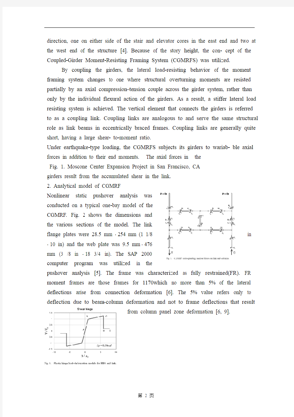
2. Analytical model of CGMRF
Nonlinear static pushover analysis was
conducted on a typical one-bay model of the
CGMRF. Fig. 2 shows the dimensions and
the various sections of the model. The link
flange plates were 28.5 mm ? 254 mm (1 1/8 in ? 10 in) and the web plate was 9.5 mm ? 476
mm (3 /8 in ? 18 3/4 in). The SAP 2000
computer program was utilized in the
pushover analysis [5]. The frame was characterized as fully restrained(FR). FR moment frames are those frames for 1170which no more than 5% of the lateral deflections arise from connection deformation [6]. The 5% value refers only to deflection due to beam–column deformation and not to frame deflections that result
from column panel zone deformation [6, 9].
The analysis was performed using an expected value
of the yield stress and ultimate strength. These values
were equal to 372 MPa (54 ksi) and 518 MPa (75 ksi),
respectively. The plastic hinges’ load–deformation
behavior was approximated by the generalized curve
suggested by NEHRP Guidelines for the Seismic
Rehabilitation of Buildings [6] as shown in.Fig. 3. △y
was calcu- lated based on Eqs. (5.1) and (5.2) from
[6], as follows:
P–M hinge load–deformation model points C, D and E are based on Table 5.4 from [6] for △y was taken as 0.01 rad per Note 3 in [6], Table 5.8. Shear hinge load- load–deformation model points C, D and E are based on Table 5.8 [6], Link Beam, Item a. A strain hardening slope between points B and C of 3% of the elastic slope was assumed for both models.
The following relationship was used to account for moment–axial load interaction [6]:
where MCE is the expected moment strength, ZRBS is the RBS plastic section modulus (in3), is the expected yield strength of the material (ksi), P is the axial force in the girder (kips) and is the expected axial yield force of the RBS, equal to (kips). The ultimate flexural capacities of the beam and the link of the model are shown in Table 1.
Fig. 4 shows qualitatively the distribution of the bending moment, shear force, and axial force in the CGMRF under lateral load. The shear and axial force in the beams are less significant to the response of the beams as compared with the bending moment, although they must be considered in design. The qualita- tive distribution of internal forces illustrated in Fig. 5 is fundamentally the same for both elastic and inelastic ranges of behavior. The specific values of the internal forces will change as elements of the frame yield and internal for- ces are redistributed. The basic patterns illustrated in Fig. 5, however, remain the same.
Inelastic static pushover analysis was carried out by applying monotonically increasing lateral displacements, at the top of both columns, as shown in Fig. 6. After the four RBS have yielded simultaneously, a uniform yielding in the web and at the ends of the flanges of the vertical link will form. This is the yield mechanism for the frame , with plastic hinges also forming at the base of the columns if they are fixed. The base shear versus drift angle of the model is shown in Fig. 7 . The sequence of
inelastic activity in the frame is shown on the figure. An elastic component, a long transition (consequence of the beam plastic hinges being formed simultaneously) and a narrow yield plateau characterize the pushover curve.
The plastic rotation capacity, qp, is defined as the total plastic rotation beyond which the connection strength starts to degrade below 80% [7]. This definition is different from that outlined in Section 9 (Appendix S) of the AISC Seismic Provisions [8, 10]. Using Eq. (2) derived by Uang and Fan [7], an estimate of the RBS plastic rotation capacity was found to be 0.037 rad:
Fyf was substituted for Ry?Fy [8], where Ry is used to account for the differ- ence between the nominal and the expected yield strengths (Grade 50 steel, Fy=345 MPa and Ry =1.1 are used).
3.Experimental program
The experimental set-up for studying the behavior of a connection was based on Fig. 6(a). Using the plastic displacement dp, plastic rotation gp, and plastic story drift angle qp shown in the figure, from geometry, it follows that:And: in which d and g include the elastic components. Approximations as above are used for large inelastic beam deformations. The diagram in Fig. 6(a) suggest that a sub assemblage with displacements controlled in the manner shown in Fig. 6(b) can represent the inelastic behavior of a typical beam in a CGMRF.
The test set-up shown in Fig. 8 was
constructed to develop the mechanism shown in
Fig. 6(a) and (b). The axial actuators were
attached to three 2438 mm × 1219 mm × 1219
mm (8 ft × 4 ft × 4 ft) RC blocks. These blocks
were tensioned to the laboratory floor by means
of twenty-four 32 mm diameter dywidag rods. This arrangement permitted replacement of the specimen after each test.
Therefore, the force applied by the axial actuator, P, can be resolved into two or thogonal components, Paxial and Plateral. Since the inclination angle of the axial actuator does not exceed 3.0 , therefore Paxial is approximately equal to P [4]. However, the lateral component, Plateral, causes an additional moment at the beam-to column joint. If the axial actuators compress the specimen, then the lateral components will be adding to the lateral actuator forces, while if the axial actuators pull the specimen, the Plateral will be an opposing force to the lateral actuators. When the axial actuators undergo
axial actuators undergo a lateral displacement _, they cause an additional moment at the beam-to-column joint (P-△ effect). Therefore, the moment at the beam-to column joint is equal to:
where H is the lateral forces, L is the arm, P is the axial force and _ is the lateral displacement.
Four full-scale experiments of beam column connections were conducted.
The member sizes and the results of tensile coupon tests are listed in Table 2
All of the columns and beams were of A572 Grade 50 steel (Fy 344.5 MPa). The actual measured beam flange yield stress value was equal to 372 MPa (54 ksi), while the ultimate strength ranged from 502 MPa (72.8 ksi) to 543 MPa (78.7 ksi).
Table 3 shows the values of the plastic moment for each specimen (based on measured tensile coupon data) at the full cross-section and at the reduced section at mid-length of the RBS cutout.
The specimens were designated as specimen 1 through specimen 4. Test specimens details are shown in Fig. 9 through Fig. 12. The following features were utilized in the design of the beam–column connection:
The use of RBS in beam flanges. A circular cutout was provided, as illustr- ated in Figs. 11 and 12. For all specimens, 30% of the beam flange width was removed. The cuts were made carefully, and then ground smooth in a direct- tion parallel to the beam flange to minimize notches.
Use of a fully welded web connection. The connection between the beam web and the column flange was made with a complete joint penetration groove weld (CJP). All
CJP welds were performed according to AWS D1.1 Structural Welding Code
Use of two side plates welded with CJP to exterior sides of top and bottom beam flan- ges, from the face of the column flange to the beginning of the RBS, as shown in Figs. 11 and 12. The end of the side plate was smoothed to meet the beginning of the RBS. The side plates were welded with CJP with the column flanges. The side plate was added to increase the flexural capacity at the joint location, while the smooth transition was to reduce the stress raisers, which may initiate fracture.
Two longitudinal stiffeners, 95 mm ×35 mm
(3 3/4 in ×1 3/8 in), were welded with 12.7 mm
(1/2 in) fillet weld at the middle height of the web
as shown in Figs. 9 and 10. The stiffeners were
welded with CJP to column flanges.
Removal of weld tabs at both the top and bottom
beam flange groove welds. The weld tabs were
removed to eliminate any potential notches
introduced by the tabs or by weld discontinuities
in the groove weld run out regions.
Use of continuity plates with a thickness approximately equal to the beam flange thickness. One-inch thick continuity plates were used for all specimens.
While the RBS is the most distinguishing feature of these test specimens, the longitudinal stiffener played an important role in delaying the formation of web local buckling and developing reliable connection performance4. Loading history Specimens were tested by applying cycles of alternated load with tip displacement increments of _y as shown in Table 4. The tip displacement of the beam was imposed by servo-controlled actuators 3 and 4. When the axial force was to be applied, actuators 1 and 2 were activated such that its force simulates the shear force in the link to be transferred to the beam. The variable axial force was increased up to 2800 kN (630 kip) at 0.5_y. After that, this lo- ad was maintained constant through the maximum lateral displacement.
maximum lateral displacement. As the specimen was pushed back the axial force remained constant until 0.5 y and then started to decrease to zero as the specimen passed through the neutral position [4]. According to the upper bound for beam axial force as discussed in Section 2 of this paper, it was concluded that P
=2800 kN (630 kip) is appropriate to investigate this case in RBS loading. The tests were continued until failure of the specimen, or until limitations of the test set-up were reached.
5. Conclusions
Based on the observations made during the tests, and on the analysis of the instrumentation, the following conclusions were developed:
1. The plastic rotation exceeded the 3% radians in all test specimens.
2. Plastification of RBS developed in a stable manner.
3. The overstrength ratios for the flexural strength of the test specimens were equal to 1.56 for specimen 1 and 1.51 for specimen
4. The flexural strength capacity was based on the nominal yield strength and on the FEMA-273 beam–column equation. 4. Although flange local buckling did not cause an immediate degradation of strength, it did induce web local buckling
5. The plastic local buckling of the bottom flange and the web was not accompanied by a significant deterioration in the load-carrying capacity.
6. The longitudinal stiffener added in the middle of the beam web assisted in transferring the axial forces and in delaying the formation of web local buckling. How ever, this has caused a much higher overstrength ratio, which had a significant impact on the capacity design of the welded joints, panel zone and the column.
7. A gradual strength reduction occurred after 0.015 to 0.02 rad of plastic rotation during negative cycles. No strength degradation was observed during positive cycles.
8. Compression axial load under 0.0325Py does not affect substantially the connection deformation capacity.
9. CGMRFS with properly designed and detailed RBS connections is a reliable system to resist earthquakes.
弯钢框架结点在轴向变化
荷载和侧向位移的作用下的周期性行为
摘自:钢结构研究杂志。59卷1号,一月,2003 摘要:这篇论文讨论的是在变化的轴向荷载和侧向位移的作用下,接受测试的四种受弯钢结点的周期性行为。梁的试样由变截面梁,翼缘以及纵向的加劲肋组成。受测试样加载轴向荷载和侧向位移用以模拟侧向荷载对组合梁抗弯系统的影响。实验结果表明试样在旋转角度超过0.03弧度后经历了从塑性到延性的变化。纵向加劲肋的存在帮助传递轴向荷载以及延缓腹板的局部弯曲。
1、引言
为了评价变截面梁(RBS)结点在轴向荷载和侧向位移下的结构性能,对四个全尺寸的样品进行了测试。这些测试打算评价为旧金山展览中心扩建设计的受弯结点在满足设计基本地震等级(DBE)和最大可能地震等级(MCE)下的性能。基于上述而做的对RBS受弯结点的研究指出RBS形式的结点能够获得超过0.03弧度的旋转角度。然而,有人对于这些结点在轴向和侧向荷载作用下的抗震性能质量提出了怀疑。
旧金山展览中心扩建工程是一个3层构
造,并以钢受弯框架作为基本的侧向力抵抗
系统。Fig.1是一幅三维透视图。建筑的总标
高为展览厅屋顶的最高点,大致是35.36m
(116ft)。展览厅天花板的高度是8.23m
(27ft),层高为11.43m(37.5ft)。建筑物
按照1997统一建筑规范设计。
框架系统由以下几部分组成:四个东西走向的受弯框架,每个电梯塔边各一个;四个走向的受弯框架,在每个楼梯和电梯井各一个的;整体分布在建筑物的东西两侧。考虑到层高的影响,提出了双梁抗弯框架系统的观念。
通过连接大梁,受弯框架系统的抵抗荷载的行为转化为结构倾覆力矩部分地被梁系统的轴向压缩-拉伸分担,而不是仅仅通过梁的弯曲。结果,达到了一个刚性侧向荷载抵抗系统。竖向部分与梁以联结杆的形式连接。联结杆在结构中模拟偏心刚性构架并起到与其相同的作用。通常地联结杆都很短,并有很大的剪弯比。
在地震类荷载的作用下,CGMRFS梁的最终弯矩将考虑到可变轴向力的影响。梁中的轴向力是切向力连续积累的结果。
2.CGMRF的解析模型
非线性静力推出器模型是以典型的单间CGMRF模板为指导。模型的尺寸规格
和多个部分。翼缘板尺寸为28.5mm ?254mm (1 1/8in ?10in ),腹板尺寸为
9.5mm ?476mm (3/8in ?18 3/4in )。推进器模型中运用了SAP 2000计算机程序。框架的特色是全约束(FR )。FR 受弯框架是一种由结点应变引起的挠度不超过侧向挠度的5%的框架。这个5%仅与梁-柱应变有关,而与柱底板区应变引起的框架应变无关。
模型通过屈服应力和匹配强度的期望值
来运行。这些值各自为372Mpa (54ksi )和
518Mpa (75ksi )。Fig.3显示了塑性铰的荷
载-应变行为是通过建筑物地震恢复的NEHRP
指标以广义曲线的形式逼近的。?y 以Eps5.1
和5.2为基底运算,如下:
P-M 铰合线荷载-应变模型上的点C ,D 和E 的取值如表5.4
?y 以0.01rad 为幅度取值见表5.8。切变铰合线荷载-应变模型点C ,D 和E 取值见表5.8。对于连续梁,假定两个模型点B 和C 之间的形变硬化比有3%的弹性比。
用下面的公式计算弯矩与轴向荷载之间的相互关系
CE M 是期望弯矩强度,RBS Z 是RBS 塑性模量,ye F 是材料的屈服强度,P 是梁中的轴向力,ye P 是RBS 屈服力,等于g A ye F 。梁的最终弯曲能力和模型的连续行见图1。
Fig.4定性的给出了侧向荷载下的CGMRF 中的弯矩,切应力和正应力的分布。其中切应力和正应力对梁的影响要小于弯矩的作用,尽管他们必须在设计中加以考虑。内力分布图解见Fig.5,可见,弹性范围和非弹性范围的内力行为基本相同。内力的比值将随框架的屈服和内力的重分布的变化而变化。基本内力图见Fig.5,然而,仍然是一样的。
非静力推进器模型的运行通过柱子顶部的侧向位移的单调增加来实现,如
Fig.5所示。在四个RBS 同时屈服后,发
生在腹板与翼缘端部的竖向的统一屈服将开
始形成。这是框架的屈服中心,在柱子被固定
后将在柱底部形成塑性铰。Fig.7给出了基本
切应力偏移角。图中还给出了框架中非弹性活
动的次序。对于一个弹性组成,推进器将有一
个特有的很长的过渡(同时形成塑性铰)和一
个很短的屈服平稳阶段。
塑性旋转能力,p 被定义为:结点强度从开始递减到低于80%的总的塑性旋转角。这个定义不同于第9段(附录)AISC 地震条款的描述。使用Eq 源于RBS 塑性旋转能力被定在0.037弧度。
yf F 被y y R F 替代,y R 用来计算理论屈服强度与实际屈服强度的区别(标号是50钢)
3.实践规划
如图6所示,实验布置是为了研究基于典型的CGMRF 结构下的结点在动力学中的能量耗散。用图中所给的塑性位移,塑性转角,塑性偏移角,由几何结构,有如下:
和
这里的δ和γ包括了弹性组合。上述近似值用于大型的非弹性梁的变形破坏。图6a 表明用图6b 所示的位移控制下的替代组合能够表示CGMRF 结构中的典型梁的非弹性行为。
图8所示,建立这个实验装置来发展图6a
和图6b 所示的机构学。轴心装置附以3个2438mm
×1219mm ×1219mm (8ft ×4ft ×4ft )RC 块。并
用24个32mm 径的杆与实验室的地板固定。这种
装置允许在每次测验后换实验样品。
根据实验布置的动力学要求,随着侧面的元件放置,轴向的元件,元件1和元件2,将钉到B 和C 中去, 如图8所示。因此,轴向元件提供的轴向力P 可以被分解为相互正交的力的组合,axial P 和lateral P ,由于轴向力的倾斜角度不超过3.0,因此axial P 近似等于P 。然而,侧向力分量,lateral P ,引起了一个在梁柱交接
处的附加弯矩。如果轴向元件压试样的话,那么lateral P 将会加到侧向力中,若轴
向是拉力,对于侧向元件来说则是个反向力。当轴向元件有个侧向位移?,他们将在梁柱交接处引起一个附加弯矩,因此,梁柱交接处的弯矩等于:
M=HL+P ?
其中H 是侧向力,L 是力臂,P 是轴向力,?是侧向位移。
四个梁柱结点全尺寸实验做完了。拉伸试样检测的结果和构件尺寸见表2。所有柱和梁的钢筋为A572标号50钢(y F =344.5Mpa )。经测定的梁翼缘屈服应力值等于372Mpa (54ksi ),整体的强度范围是从502Mpa (72.8ksi )到543Mpa (78.7ksi )。
表3列出了各个试样的全截面和RBS 中间变截面处的塑性弯矩值(受拉应力下的数据)。
本文所指的试样专指试样1到4。被检试样细部图见图9到图12。在设计梁柱结点时用到了以下数据:
梁翼缘部分采用RBS 结构。配备环形掏槽,如图11和图12所示。对于所有的试样,切除30%翼缘宽度。切除工作做的十分精细,并打磨光滑且与梁翼缘保持平行以尽量见效切口。
应用全焊接腹板结点。梁腹板与柱翼缘之间的结点采用全焊缝焊接(CJP )。所有CJP 焊接严格依照AWS D1.1结构焊接规范。
采用双侧板加CJP 形式连接梁翼缘的顶部和底部和柱表面到变截面开始处,如图11和图12。侧板尾部打磨光滑以便同RBS 连接。侧板采用CJP 形式与柱边缘相连接。侧板的作用是增加受弯单元的承受能力,平稳过渡是为了减少应力集中而导致的破裂。
两根纵向的加劲肋,95mm×35mm(3 3/4in ×
1 3/8 in),以12.7mm的角焊缝焊接到腹板中间
高度,如图9和10。加劲肋采用CJP的形式焊接
到柱的边缘。
切除梁翼缘顶部和低部的坡口焊缝处的焊接
部分。以便消除坡口焊接断口处可能产生的断裂。
除去翼缘低部的衬垫板条。以便消除衬垫板
条带来的断口效应并增加安全性。
使用与梁翼缘厚度近似相同的连续板。所有
试样板厚均为一英寸。
由于RBS是受检试样最容易区分的特征,纵向的加劲肋在延缓局部弯曲和提高可靠性方面扮演着重要的角色。
4.荷载历史
试样被加以周期性交替的荷载,其末端的位移△y的增加如图4所示。梁的末端位移受伺服控制装置3和4的影响。当作用轴向力时,制动器1和2是活动的,以用它的受力来模拟从连接处传到梁上的剪力。可变的轴向荷载在+0.5△y 处增加到2800KN。在那以后,通过最大的侧向位移,这个荷载保持恒定。在试样被推回时,轴向力维持恒定直至0.5△y,然后减小到零,此时的试样通过中和轴。根据本文第2部分有关轴向力受以上约束的论述,可以推断出以P=2800KN 来研究RBS负载是合理的。测试将会继续,直至试样损坏,或者到实验预期的限制。
5.结论
基于由实验而得的数据,以及应用于仪器的解析法,得出如下结论:
1、对于所有的试样,塑性旋度均超出0.3%。
2、 RBS的塑性过程是平稳发展的。
3、试样超出抗弯强度的比率,试样1等于 1.56,试样4等于 1.51。抗弯强度承载能力取决于标定的屈服强度和FEMA-273梁-柱等式。
4、底缘和腹板的塑性局部弯曲对其荷载承受能力没有重大的削弱。
5、尽管翼缘的局部弯曲不使强度立即产生削弱,但是它确实导致腹板的局部弯曲。
6、设置在梁的腹板中部的纵向加劲肋,能够帮助传递轴向力,还能延缓腹板的局部弯曲。然而,它却产生如此大的一个超过强度的比率,从而使焊接结点、板条区域以及柱子的承载能力在设计时大打折扣。
7、在负载周期时,塑性旋度为0.015到0.02rad时将会产生一个逐渐的强度的减弱。在正向周期时也没有。
8、轴想压缩荷载在小于0.0325Py时,对结点应变能力影响不大。
9、 CGMRFS技术与适当的设计以及详细的RBS连接,是一个可靠的抗震系统。
土木工程类专业英文文献及翻译
PA VEMENT PROBLEMS CAUSED BY COLLAPSIBLE SUBGRADES By Sandra L. Houston,1 Associate Member, ASCE (Reviewed by the Highway Division) ABSTRACT: Problem subgrade materials consisting of collapsible soils are com- mon in arid environments, which have climatic conditions and depositional and weathering processes favorable to their formation. Included herein is a discussion of predictive techniques that use commonly available laboratory equipment and testing methods for obtaining reliable estimates of the volume change for these problem soils. A method for predicting relevant stresses and corresponding collapse strains for typical pavement subgrades is presented. Relatively simple methods of evaluating potential volume change, based on results of familiar laboratory tests, are used. INTRODUCTION When a soil is given free access to water, it may decrease in volume, increase in volume, or do nothing. A soil that increases in volume is called a swelling or expansive soil, and a soil that decreases in volume is called a collapsible soil. The amount of volume change that occurs depends on the soil type and structure, the initial soil density, the imposed stress state, and the degree and extent of wetting. Subgrade materials comprised of soils that change volume upon wetting have caused distress to highways since the be- ginning of the professional practice and have cost many millions of dollars in roadway repairs. The prediction of the volume changes that may occur in the field is the first step in making an economic decision for dealing with these problem subgrade materials. Each project will have different design considerations, economic con- straints, and risk factors that will have to be taken into account. However, with a reliable method for making volume change predictions, the best design relative to the subgrade soils becomes a matter of economic comparison, and a much more rational design approach may be made. For example, typical techniques for dealing with expansive clays include: (1) In situ treatments with substances such as lime, cement, or fly-ash; (2) seepage barriers and/ or drainage systems; or (3) a computing of the serviceability loss and a mod- ification of the design to "accept" the anticipated expansion. In order to make the most economical decision, the amount of volume change (especially non- uniform volume change) must be accurately estimated, and the degree of road roughness evaluated from these data. Similarly, alternative design techniques are available for any roadway problem. The emphasis here will be placed on presenting economical and simple methods for: (1) Determining whether the subgrade materials are collapsible; and (2) estimating the amount of volume change that is likely to occur in the 'Asst. Prof., Ctr. for Advanced Res. in Transp., Arizona State Univ., Tempe, AZ 85287. Note. Discussion open until April 1, 1989. To extend the closing date one month,
土木工程专业英语翻译
a common way to construct steel truss and prestressed concrete cantilever spans is to counterbalance each cantilever arm with another cantilever arm projecting the opposite direction,forming a balanced cantilever. they attach to a solid foundation ,the counterbalancing arms are called anchor arms /thus,in a bridge built on two foundation piers,there are four cantilever arms ,two which span the obstacle,and two anchor arms which extend away from the obstacle,because of the need for more strength at the balanced cantilever's supports ,the bridge superstructure often takes the form of towers above the foundation piers .the commodore barry bridge is an example of this type of cantilever bridge 一种常见的方法构造钢桁架和预应力混凝土悬臂跨度是每一个悬臂抗衡预测相反的方向臂悬臂,形成一个平衡的悬臂。他们重视了坚实的基础,制约武器被称为锚武器/因此,在两个基础上建一座桥桥墩,有四个悬臂式武器,这两者之间跨越的障碍,和两个锚武器哪个延长距离的障碍,因为为更多的在平衡悬臂的支持力量的需要,桥梁上部结构往往表现为塔墩基础之上形成的准将巴里大桥是这种类型的例子悬臂桥 steel truss cantilever support loads by tension of the upper members and compression of the lower ones .commonly ,the structure distributes teh tension via teh anchor arms to the outermost supports ,while the compression is carried to the foundation beneath teh central towers .many truss cantilever bridges use pinned joints and are therefore statically determinate with no members carrying mixed loads 钢桁架悬臂由上层成员和下层的紧张压缩支持负载。通常,结构分布通过锚武器的最外层的支持紧张,而压缩抬到下方的中央塔的基础。桁架悬臂许多桥梁使用固定的关节,是静定,没有携带混合负载的成员,因此 prestressed concrete balanced cantilever bridges are often built using segmental construction .some steel arch bridges are built using pure cantilever spans from each sides,with neither falsework below nor temporary supporting towers and cables above ,these are then joined with a pin,usually after forcing the union point apart ,and when jacks are removed and the bridge decking is added the bridge becomes a truss arch bridge .such unsupported construction is only possible where appropriate rock is available to support the tension in teh upper chord of the span during construction ,usually limiting this method to the spanning of narrow canyons 预应力混凝土平衡悬臂桥梁往往建立使用段施工。一些钢拱桥是使用各方面的纯悬臂跨度既无假工作下面也临时支撑塔和电缆上面,这些都是再加入了一根针,通常在迫使工会点外,当插孔删除,并添加桥梁甲板桥成为桁架拱桥,这种不支持的建设,才可能在适当情况下的岩石可用于支持在施工期间的跨度弦上的张力,通常限制这狭隘的峡谷跨越方法 an arch bridge is a bridge with abutments at each end shaped as a curved arch .arch bridges work by transferring the weight of the bridge and its loads partially into a horizontal thrust restrained by the abutments at either side .a viaduct may be made from a series of arches ,although other more economical structures are typically used today 在拱桥桥台的桥梁,是一个在一个弧形拱状,每年年底。拱桥通过转移到由部分在两边的桥台水平推
土木工程岩土类毕业设计外文翻译
姓名: 学号: 10447425 X X 大学 毕业设计(论文)外文翻译 (2014届) 外文题目Developments in excavation bracing systems 译文题目开挖工程支撑体系的发展 外文出处Tunnelling and Underground Space Technology 31 (2012) 107–116 学生XXX 学院XXXX 专业班级XXXXX 校内指导教师XXX 专业技术职务XXXXX 校外指导老师专业技术职务 二○一三年十二月
开挖工程支撑体系的发展 1.引言 几乎所有土木工程建设项目(如建筑物,道路,隧道,桥梁,污水处理厂,管道,下水道)都涉及泥土挖掘的一些工程量。往往由于由相邻的结构,特性线,或使用权空间的限制,必须要一个土地固定系统,以允许土壤被挖掘到所需的深度。历史上,许多挖掘支撑系统已经开发出来。其中,现在比较常见的几种方法是:板桩,钻孔桩墙,泥浆墙。 土地固定系统的选择是由技术性能要求和施工可行性(例如手段,方法)决定的,包括执行的可靠性,而成本考虑了这些之后,其他问题也得到解决。通常环境后果(用于处理废泥浆和钻井液如监管要求)也非常被关注(邱阳、1998)。 土地固定系统通常是建设项目的较大的一个组成部分。如果不能按时完成项目,将极大地影响总成本。通常首先建造支撑,在许多情况下,临时支撑系统是用于支持在挖掘以允许进行不断施工,直到永久系统被构造。临时系统可以被去除或留在原处。 打桩时,因撞击或振动它们可能会被赶入到位。在一般情况下,振动是最昂贵的方法,但只适合于松散颗粒材料,土壤中具有较高电阻(例如,通过鹅卵石)的不能使用。采用打入桩系统通常是中间的成本和适合于软沉积物(包括粘性和非粘性),只要该矿床是免费的鹅卵石或更大的岩石。 通常,垂直元素(例如桩)的前安装挖掘工程和水平元件(如内部支撑或绑回)被安装为挖掘工程的进行下去,从而限制了跨距长度,以便减少在垂直开发弯矩元素。在填充情况下,桩可先设置,从在斜坡的底部其嵌入悬挑起来,安装作为填充进步水平元素(如搭背或土钉)。如果滞后是用来保持垂直元素之间的土壤中,它被安装为挖掘工程的进行下去,或之前以填补位置。 吉尔- 马丁等人(2010)提供了一个数值计算程序,以获取圆形桩承受轴向载荷和统一标志(如悬臂桩)的单轴弯矩的最佳纵筋。他们开发的两种优化流程:用一个或两个直径为纵向钢筋。优化增强模式允许大量减少的设计要求钢筋的用量,这些减少纵向钢筋可达到50%相对传统的,均匀分布的加固方案。 加固桩集中纵向钢筋最佳的位置在受拉区。除了节约钢筋,所述非对称加强钢筋图案提高抗弯刚度,通过增加转动惯量的转化部分的时刻。这种增加的刚性可能会在一段时间内增加的变形与蠕变相关的费用。评估相对于传统的非对称加强桩的优点,对称,钢筋桩被服务的条件下全面测试来完成的,这种试验是为了验证结构的可行性和取得的变形的原位测量。 基于现场试验中,用于优化的加强图案的优点浇铸钻出孔(CIDH)在巴塞罗那的
土木工程专业英语原文及翻译
土木工程专业英语原文 及翻译 文档编制序号:[KKIDT-LLE0828-LLETD298-POI08]
08 级土木(1) 班课程考试试卷 考试科目专业英语 考试时间 学生姓名 所在院系土木学院 任课教师 徐州工程学院印制 Stability of Slopes Introduction Translational slips tend to occur where the adjacent stratum is at a relatively shallow depth below the surface of the slope:the failure surface tends to be plane and roughly parallel to the slips usually occur where the adjacent stratum is at greater depth,the failure surface consisting of curved and plane sections. In practice, limiting equilibrium methods are used in the analysis of slope stability. It is considered that failure is on the point of occurring along an assumed or a known failure surface.The shear strength required to maintain a condition of limiting equilibrium is compared with the available shear strength of the soil,giving the average factor of safety along the failure surface.The problem is considered in two dimensions,conditions of plane strain being assumed.It has been shown that a two-dimensional analysis gives a conservative result for a failure on a three-dimensional(dish-shaped) surface. Analysis for the Case of φu =0 This analysis, in terms of total stress,covers the case of a fully saturated clay under undrained conditions, . For the condition immediately after construction.Only moment equilibrium is considered in the analysis.In section, the potential failure surface is assumed to be a circular arc. A trial failure surface(centre O,radius r and length L a where F is the factor of safety with respect to shear strength.Equating moments about O:
土木工程专业外文文献及翻译
( 二 〇 一 二 年 六 月 外文文献及翻译 题 目: About Buiding on the Structure Design 学生姓名: 学 院:土木工程学院 系 别:建筑工程系 专 业:土木工程(建筑工程方向) 班 级:土木08-4班 指导教师:
英文原文: Building construction concrete crack of prevention and processing Abstract The crack problem of concrete is a widespread existence but again difficult in solve of engineering actual problem, this text carried on a study analysis to a little bit familiar crack problem in the concrete engineering, and aim at concrete the circumstance put forward some prevention, processing measure. Keyword:Concrete crack prevention processing Foreword Concrete's ising 1 kind is anticipate by the freestone bone, cement, water and other mixture but formation of the in addition material of quality brittleness not and all material.Because the concrete construction transform with oneself, control etc. a series problem, harden model of in the concrete existence numerous tiny hole, spirit cave and tiny crack, is exactly because these beginning start blemish of existence just make the concrete present one some not and all the characteristic of quality.The tiny crack is a kind of harmless crack and accept concrete heavy, defend Shen and a little bit other use function not a creation to endanger.But after the concrete be subjected to lotus carry, difference in temperature etc. function, tiny crack would continuously of expand with connect, end formation we can see without the
土木中英翻译
2.4 开启功能修复 解放桥中跨为开启跨,开启系统为施尔泽尔(Scherzer)式。这一系统通过电动机的动力输送,由齿轮组、动轮、齿条、弧形梁、平衡重密切的配合运动,使得末端齿轮轴的水平移动转化成扇形齿在固定齿梁上的滚动,这一随着开启角度而变化的转动轴,使桥梁在开启过程中,整个开启跨结构围绕转动轴处于受力的平衡状态,使桥梁有控制地徐徐向后仰起完成开启动作。桥梁开启后,两墩之间有42.7m的自由航道。 2.4 Repairing of the movable function The middle span of Liberation Bridge is a movable span whose movable system is Scherzer’s pattern. The opening system is driven by an electric motor. With the team motion of gear set, driving wheel, rack, curved beam and balance weight, horizontal motion of the gear shaft can be converted to be the roll of gear sector on fixed gear whose position varies with opening angle. Bridge structure is on the state of equilibrium with respect to the rotation axis when opening, which make it possible to open the bridge deck gradually in a controllable way. The width of free waterway is about 42.7m after bridge deck is opened. 解放桥开启系统严格按照原开启方式恢复,主要通过三步工作来实现。 1.通过实地考察、勘查与了解,明确解放桥的开启系统原理,完成开启系统的设计工作。 The opening system is repaired strictly according to the former opening pattern, and the repairing procedure can be divided into three steps as follows: 1. After field investigation and exploration, design the opening system with clearly comprehending the principle of opening system of Liberation Bridge. 2.安装调试 (1).车间内初安装调试 在车间内首先对每个传动部件进行初安装,调整好齿轮、支承件的位置与间隙,并在各个支承部件处加润滑脂,保证部件转动灵活;在车间内搭设辅助初调试平台,将所有上桥传动部件放在车间内的辅助初调试平台上,单侧活动跨的整体传动系统联接安装初调试,调整好各对齿轮间的位置与间隙,并在各个支承部件处加润滑脂,使得系统转动灵活,检查全部零部件并确认无遗漏情况。 2 Installation debugging (1) Initially installation debugging in workshop Every transmission part should be initially installed firstly in workshop. In this stage, the position of each gear and strutting piece should be adjusted and lubricating oil should be applied to each strutting piece to make sure their free rotation. Then all the transmission parts should be placed on the auxiliary initial debugging platform in
土木工程专业英语课文原文及对照翻译
土木工程专业英语课文原 文及对照翻译 Newly compiled on November 23, 2020
Civil Engineering Civil engineering, the oldest of the engineering specialties, is the planning, design, construction, and management of the built environment. This environment includes all structures built according to scientific principles, from irrigation and drainage systems to rocket-launching facilities. 土木工程学作为最老的工程技术学科,是指规划,设计,施工及对建筑环境的管理。此处的环境包括建筑符合科学规范的所有结构,从灌溉和排水系统到火箭发射设施。 Civil engineers build roads, bridges, tunnels, dams, harbors, power plants, water and sewage systems, hospitals, schools, mass transit, and other public facilities essential to modern society and large population concentrations. They also build privately owned facilities such as airports, railroads, pipelines, skyscrapers, and other large structures designed for industrial, commercial, or residential use. In addition, civil engineers plan, design, and build complete cities and towns, and more recently have been planning and designing space platforms to house self-contained communities. 土木工程师建造道路,桥梁,管道,大坝,海港,发电厂,给排水系统,医院,学校,公共交通和其他现代社会和大量人口集中地区的基础公共设施。他们也建造私有设施,比如飞机场,铁路,管线,摩天大楼,以及其他设计用作工业,商业和住宅途径的大型结构。此外,土木工程师还规划设计及建造完整的城市和乡镇,并且最近一直在规划设计容纳设施齐全的社区的空间平台。 The word civil derives from the Latin for citizen. In 1782, Englishman John Smeaton used the term to differentiate his nonmilitary engineering work from that of the military engineers who predominated at the time. Since then, the term civil engineering has often been used to refer to engineers who build public facilities, although the field is much broader 土木一词来源于拉丁文词“公民”。在1782年,英国人John Smeaton为了把他的非军事工程工作区别于当时占优势地位的军事工程师的工作而采用的名词。自从那时起,土木工程学被用于提及从事公共设施建设的工程师,尽管其包含的领域更为广阔。 Scope. Because it is so broad, civil engineering is subdivided into a number of technical specialties. Depending on the type of project, the skills of many kinds of civil engineer specialists may be needed. When a project begins, the site is surveyed and mapped by civil engineers who locate utility placement—water, sewer, and power lines. Geotechnical specialists perform soil experiments to determine if the earth can bear the weight of the project. Environmental specialists study the project’s impact on the local area: the potential for air and
土木工程专业英语翻译(武汉理工大学出版社段兵廷主编)完整版
第一课土木工程学 土木工程学作为最老的工程技术学科,是指规划,设计,施工及对建筑环境的管理。此处的环境包括建筑符合科学规范的所有结构,从灌溉和排水系统到火箭发射设施。 土木工程师建造道路,桥梁,管道,大坝,海港,发电厂,给排水系统,医院,学校,公共交通和其他现代社会和大量人口集中地区的基础公共设施。他们也建造私有设施,比如飞机场,铁路,管线,摩天大楼,以及其他设计用作工业,商业和住宅途径的大型结构。此外,土木工程师还规划设计及建造完整的城市和乡镇,并且最近一直在规划设计容纳设施齐全的社区的空间平台。 土木一词来源于拉丁文词“公民”。在1782年,英国人John Smeaton为了把他的非军事工程工作区别于当时占优势地位的军事工程师的工作而采用的名词。自从那时起,土木工程学被用于提及从事公共设施建设的工程师,尽管其包含的领域更为广阔。 领域。因为包含范围太广,土木工程学又被细分为大量的技术专业。不同类型的工程需要多种不同土木工程专业技术。一个项目开始的时候,土木工程师要对场地进行测绘,定位有用的布置,如地下水水位,下水道,和电力线。岩土工程专家则进行土力学试验以确定土壤能否承受工程荷载。环境工程专家研究工程对当地的影响,包括对空气和地下水的可能污染,对当地动植物生活的影响,以及如何让工程设计满足政府针对环境保护的需要。交通工程专家确定必需的不同种类设施以减轻由整个工程造成的对当地公路和其他交通网络的负担。同时,结构工程专家利用初步数据对工程作详细规划,设计和说明。从项目开始到结束,对这些土木工程专家的工作进行监督和调配的则是施工管理专家。根据其他专家所提供的信息,施工管理专家计算材料和人工的数量和花费,所有工作的进度表,订购工作所需要的材料和设备,雇佣承包商和分包商,还要做些额外的监督工作以确保工程能按时按质完成。 贯穿任何给定项目,土木工程师都需要大量使用计算机。计算机用于设计工程中使用的多数元件(即计算机辅助设计,或者CAD)并对其进行管理。计算机成为了现代土木工程师的必备品,因为它使得工程师能有效地掌控所需的大量数据从而确定建造一项工程的最佳方法。 结构工程学。在这一专业领域,土木工程师规划设计各种类型的结构,包括桥梁,大坝,发电厂,设备支撑,海面上的特殊结构,美国太空计划,发射塔,庞大的天文和无线电望远镜,以及许多其他种类的项目。结构工程师应用计算机确定一个结构必须承受的力:自重,风荷载和飓风荷载,建筑材料温度变化引起的胀缩,以及地震荷载。他
土木工程毕业设计外文翻译最终中英文
7 Rigid-Frame Structures A rigid-frame high-rise structure typically comprises parallel or orthogonally arranged bents consisting of columns and girders with moment resistant joints. Resistance to horizontal loading is provided by the bending resistance of the columns, girders, and joints. The continuity of the frame also contributes to resisting gravity loading, by reducing the moments in the girders. The advantages of a rigid frame are the simplicity and convenience of its rectangular form.Its unobstructed arrangement, clear of bracing members and structural walls, allows freedom internally for the layout and externally for the fenestration. Rig id frames are considered economical for buildings of up to' about 25 stories, above which their drift resistance is costly to control. If, however, a rigid frame is combined with shear walls or cores, the resulting structure is very much stiffer so that its height potential may extend up to 50 stories or more. A flat plate structure is very similar to a rigid frame, but with slabs replacing the girders As with a rigid frame, horizontal and vertical loadings are resisted in a flat plate structure by the flexural continuity between the vertical and horizontal components. As highly redundant structures, rigid frames are designed initially on the basis of approximate analyses, after which more rigorous analyses and checks can be made. The procedure may typically inc lude the following stages: 1. Estimation of gravity load forces in girders and columns by approximate method. 2. Preliminary estimate of member sizes based on gravity load forces with arbitrary increase in sizes to allow for horizontal loading. 3. Approximate allocation of horizontal loading to bents and preliminary analysis of member forces in bents. 4. Check on drift and adjustment of member sizes if necessary. 5. Check on strength of members for worst combination of gravity and horizontal loading, and adjustment of member sizes if necessary. 6. Computer analysis of total structure for more accurate check on member strengths and drift, with further adjustment of sizes where required. This stage may include the second-order P-Delta effects of gravity loading on the member forces and drift.. 7. Detailed design of members and connections.
土木工程英文翻译
外文文献及译文 文献、资料题目:PROTECTION AGAINST HAZARDS 院(部):建筑工程学院 专业:土木工程 班级:土木081 姓名:孙继佳 学号:200811003192 指导教师:樊江 翻译日期:2012.5.4
3.1 PROTECTION AGAINST WA TER Whether thrust against and into a building by a flood, driven into the interior by a heavy rain, leaking from plumbing, storm surge, or seeping through the exterior enclosure, water can cause costly damage to a building. Consequently, designers should protect buildings and their contents against water damage. Protective measures may be divided into two classes: floodproofing and waterproofing.Floodproofing provides protection against flowing surface water, commonly caused by a river overflowing its banks. Waterproofing provides protection against penetration through the exterior enclosure of buildings of groundwater, rainwater,and melting snow. Buildings adjacent to large water bodies may also require protection from undermining due to erosion and impact from storm driven waves. 3.4.1Floodproo?ng A ?ood occurs when a river rises above an elevation,called ?ood stage,and is not Prevented by enclosures from causing damage beyond its banks.Buildings con- Structed in a ?ood plain,an area that can be inundated by a ?ood,should be Protected against a ?ood with a mean recurrence interval of 100 years.Maps Showing ?ood-hazard areas in the United States can be obtained from the Federal InsuranceAdministrator,DepartmentofHousingandUrbanDevelopment,who Administers the National Flood Insurance Program.Minimum criteria for?ood- proo?ng are given in National Flood Insurance Rules and Regulations(Federal Register, vol.41,no.207,Oct.26,1976). Major objectives of ?oodproo?ng are to protect fully building and contents from Damage from a l00-year ?ood,reduce losses from more devastating ?oods,and Lower ?ood insurance premiums.Floodproo?ng,however,would be unnecessary if Buildings were not constructed in ?ood prone areas.Building in ?ood prone areas Should be avoided unless the risk to life is acceptable and construction there can Be economically and socially justi?ed. Some sites in flood prone areas possess some ground high enough to avoid flood damage. If such sites must be used, buildings should be clustered on the high areas. Where such areas are not available, it may be feasible to build up an earth fill, with embankments protected against erosion by water, to raise structures above flood levels. Preferably, such structures should not have basements, because they would require costly protection against water pressure. An alternative to elevating a building on fill is raising it on stilts (columns in an unenclosed space). In that case, utilities and other services should be protected against damage from flood flows. The space at ground level between the stilts may be used for parking automobiles, if the risk of water damage to them is acceptable or if they will be removed before flood waters reach the site. Buildings that cannot be elevated above flood stage should be furnished with an impervious exterior. Windows should be above flood stage, and doors should seal tightly against their frames. Doors and other openings may also be protected with a flood shield, such as a wall. Openings in the wall for access to the building may be protected with a movable flood shield, which for normal conditions can be stored